Tesla can brick your car if they want to; what makes you think Lockheed Martin can't do exactly the same with the F-35 which is required to be just as on-line for basic tasks as a damn consumer vehicle?.
You are using an out of date browser. It may not display this or other websites correctly.
You should upgrade or use an alternative browser.
You should upgrade or use an alternative browser.
South Korean Military News, Reports, Data, etc.
- Thread starter IDonT
- Start date
TerraN_EmpirE
Tyrant King
Yes does brick super charging the same way Apple does IE if you replace a part with an unauthorized part the software locks it out. If you sell it on your own and file a change of owner it locks the charger.
Yet Gentlemen, just because they may be able to doesn’t make that they do. You can claim they do all you want. Their is nothing that says they don’t nothing that says they do and the claim that they could simply clarify the position wouldn’t help as half of those who believe would insist that statement was a lie.
Next to claim that the pundit must have been read in on F35 by Chinese intelligence defies belief. I mean they might as well brief CNN. Intelligence agencies are not in the business of exposing their capabilities of espionage and knowledge of adversary capabilities to individuals not needing to know or whom are going to post it on Twitter.
It’s a leap of logic to say the least. Occam's Razor the simplest explanation is often the best. This was a tweet designed to try and inflame the ROK to question the F35 politically. Since we cannot prove an Activation Key or Kill command without a security clearance which would be violated by admission, we have a catch 22.
Boramae development news basically makes me have more positive attitude and willingness to continue living.
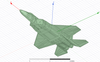
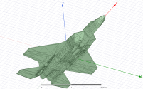
During course of its history i made myself some modelling effort mainly to predict her Radar Cross Section. I haven't renew my 3D model for it but there are some results. The one depicted here is ANSYS. I have older results calculated using POFACETS and Excel but i guess it is no longer relevant.
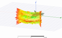
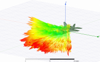
The following depicts the RCS at 90 degrees head on aspect (-45 to 45 degrees) between clean vs armed (4 meteor in semi-conformal pylon). The simulation is in X-band (8 GHz) and PEC material. no absorbers assumed.
The armed configuration shows degradation of the RCS due to interaction between missiles and the airframe. But that is to be expected.
As for the numerical value, The Median RCS for the unarmed configuration is 0.06 sqm. While the armed one is 0.15 sqm. caused by the data pool from the above graphics. In order to gauge the effect of external weapons. The "view angle" might need to be limited to the relevant aspect (e.g bottom aspect only etc).
During course of its history i made myself some modelling effort mainly to predict her Radar Cross Section. I haven't renew my 3D model for it but there are some results. The one depicted here is ANSYS. I have older results calculated using POFACETS and Excel but i guess it is no longer relevant.
The following depicts the RCS at 90 degrees head on aspect (-45 to 45 degrees) between clean vs armed (4 meteor in semi-conformal pylon). The simulation is in X-band (8 GHz) and PEC material. no absorbers assumed.
| Unarmed Configuration | Armed Configuration (Semi Conformal) |
 |  |
 |  |
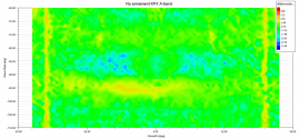 | 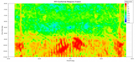 |
| Remarks : Relatively "clean" looking | Remarks : The interaction between the missiles and the airframe are evident. |
The armed configuration shows degradation of the RCS due to interaction between missiles and the airframe. But that is to be expected.
As for the numerical value, The Median RCS for the unarmed configuration is 0.06 sqm. While the armed one is 0.15 sqm. caused by the data pool from the above graphics. In order to gauge the effect of external weapons. The "view angle" might need to be limited to the relevant aspect (e.g bottom aspect only etc).
Boramae development news basically makes me have more positive attitude and willingness to continue living.
During course of its history i made myself some modelling effort mainly to predict her Radar Cross Section. I haven't renew my 3D model for it but there are some results. The one depicted here is ANSYS. I have older results calculated using POFACETS and Excel but i guess it is no longer relevant.
The following depicts the RCS at 90 degrees head on aspect (-45 to 45 degrees) between clean vs armed (4 meteor in semi-conformal pylon). The simulation is in X-band (8 GHz) and PEC material. no absorbers assumed.
Unarmed Configuration Armed Configuration (Semi Conformal) View attachment 81815 View attachment 81817 View attachment 81814 View attachment 81816 View attachment 81809 View attachment 81807 Remarks : Relatively "clean" looking Remarks : The interaction between the missiles and the airframe are evident.
The armed configuration shows degradation of the RCS due to interaction between missiles and the airframe. But that is to be expected.
As for the numerical value, The Median RCS for the unarmed configuration is 0.06 sqm. While the armed one is 0.15 sqm. caused by the data pool from the above graphics. In order to gauge the effect of external weapons. The "view angle" might need to be limited to the relevant aspect (e.g bottom aspect only etc).
Surprised that even semi-buried hardpoints could cause the RCS to balloon like that. Could you do one with wing mounted hardpoints?
Boramae development news basically makes me have more positive attitude and willingness to continue living.
During course of its history i made myself some modelling effort mainly to predict her Radar Cross Section. I haven't renew my 3D model for it but there are some results. The one depicted here is ANSYS. I have older results calculated using POFACETS and Excel but i guess it is no longer relevant.
The following depicts the RCS at 90 degrees head on aspect (-45 to 45 degrees) between clean vs armed (4 meteor in semi-conformal pylon). The simulation is in X-band (8 GHz) and PEC material. no absorbers assumed.
Unarmed Configuration Armed Configuration (Semi Conformal) View attachment 81815 View attachment 81817 View attachment 81814 View attachment 81816 View attachment 81809 View attachment 81807 Remarks : Relatively "clean" looking Remarks : The interaction between the missiles and the airframe are evident.
The armed configuration shows degradation of the RCS due to interaction between missiles and the airframe. But that is to be expected.
As for the numerical value, The Median RCS for the unarmed configuration is 0.06 sqm. While the armed one is 0.15 sqm. caused by the data pool from the above graphics. In order to gauge the effect of external weapons. The "view angle" might need to be limited to the relevant aspect (e.g bottom aspect only etc).
Do you have simulated RCS figures for the J-20 or other stealth fighters/bombers?
Do you have simulated RCS figures for the J-20 or other stealth fighters/bombers?
I have Su-57, F-35A and J-20. But the J-20 one is very crude as i only model it to show the effect of Canards.
I have Su-57, F-35A and J-20. But the J-20 one is very crude as i only model it to show the effect of Canards.
Ok. It would still be interesting to see the RCS simulations for 8 GHz for what is available.
Plus if you've already got it:
S-Band (the reserved 3.1-3.45 GHz block for US AEGIS?)
UHF (0.7? GHz for the E-2D)
