Of all the places they could have taken a clear photo of the plane, they chose the pitot tubeSome guy didn't eat fried chicken
View attachment 149698
might as well give us an 8k hdr photo of the tires at this point
Of all the places they could have taken a clear photo of the plane, they chose the pitot tubeSome guy didn't eat fried chicken
View attachment 149698
View attachment 149708
I don't know what to say about this...
idk man, not only is it ugly af it will for sure impact stealth and IWB capacity. Since the J-35 had a smooth underside this will probably have one too :copium:I can't quite see how it can work properly if it's a duct instead of an open groove, especially at higher angles of attack.
Also I'm pretty sure SAC did their homework and the groove (if it indeed exists) is a design feature that's best suited for their requirements, so personally I won't fuss over it too much
Well as I said what the jet end up having is surely what is best given the tech level available and the design requirements.idk man, not only is it ugly af it will for sure impact stealth and IWB capacity. Since the J-35 had a smooth underside this will probably have one too :copium:
Of all the places they could have taken a clear photo of the plane, they chose the pitot tube
might as well give us an 8k hdr photo of the tires at this point
Given the angle at which this photo was taken, this image - when released in its entirety - will almost certainly confirm the existence or absence of a cockpit and possibly of the ventral groove.View attachment 149708
I don't know what to say about this...
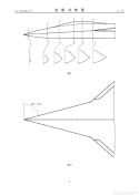
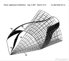
Following theasis about Biconical Bump Compression Surface.Good theory by @ from weibo. Answers our question about why no prominent bump is visible.
Hypothesis on SAC's 6th-Gen Fighter Intake Design
Initial Analysis of J-XX Photos
Current CG/line art depictions inaccurately show either:
- CARET intakes (ruled out due to absent boundary layer dividers)
- Top/mid-mounted DSI bumps (incompatible with aft-swept lips, as DSI requires forward-swept lips to create mid-bump high-pressure zones for boundary layer diversion)
Lessons from Existing Stealth Intake Designs
View attachment 149737View attachment 149735
- Airbus' Loyal Wingman
- Features: Ventral quadrilateral intake lips (classic stealth configuration)
- View attachment 149729
- View attachment 149730
- Russian Su-75 Checkmate
- Features: Shallow conical bump behind the nosecone, forming a dual-cone compression surface
- View attachment 149731
Proposed SAC Intake Structure
- Simplified Model:
- Start with a single central DSI intake
- Split vertically into twin flank-mounted DSI units
- View attachment 149734
- Key Observations:
- The V-shaped lips (side/bottom) align with blue mini-bumps for boundary layer bleed
- View attachment 149732
- Mini-bumps ride the nosecone’s lower surface, creating a dual-cone DSI system
- View attachment 149733
- Advantages:
- Higher total pressure recovery vs single-cone DSI
- Low-profile secondary bumps reduce drag + enhance stealth (mirroring the shallow canopy design)
- Integrated nosecone pre-compression + forward landing gear bay within the central bleed channel
Update: Side View Assessment
- Likely shared single bump for both intakes
- Landing gear positioned atop the bump, avoiding interference between bilateral bleed flows
January 2013
Journal of Aerospace Power
Jan. 2013
Article ID: 1000-8055(2013)01-0082-08
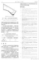
Design and Aerodynamic Characteristics of a Biconical Bump Compression Surface
WANG Long¹, ZHONG Yi-cheng¹, WU Qing², YANG Ying-kai³
(1. College of Energy and Power Engineering, Nanjing University of Aeronautics and Astronautics, Nanjing 210016, China;
2. The 38th Research Institute of China Electronics Technology Group Corporation, Hefei 230001, China;
3. Chengdu Aircraft Design & Research Institute, AVIC, Chengdu 610015, China)
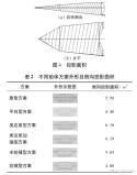
Abstract: An inverse design method was employed to investigate the design technique of a biconical bump compression surface. This method essentially involves solving the axisymmetric Euler equations under moving mesh conditions by integrating moving discontinuity boundaries. To avoid the inaccuracies of shock-capturing methods in determining shock wave profiles, a zonal computational approach was adopted to predict the second shock wave, followed by streamline tracing to generate the bump compression surface. A design example based on a flat fuselage was analyzed using viscous computational fluid dynamics (CFD) simulations. The results demonstrate that: (1) The flow field structure maintains strong boundary-layer-sweeping capability; (2) At an incoming Mach number of 2.0, compared with conventional conical reference bump designs, the new method improves the total pressure recovery coefficient of the external compression system by approximately 0.04, laying a foundation for enhanced bump inlet performance.
Key words: bump inlet; moving discontinuity boundary algorithm; inverse design method; shock-fitting; computational fluid dynamics (CFD)
CLC number: V231.1
Document code: A
