QBZ-191 service rifle family

Cabbage

Just Hatched
Registered Member
Can you explain this? I don't know enough gun knowledge to understand.
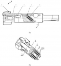
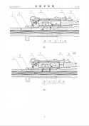
I believe the full document that contains those diagrams describes a retaining mechanism for the firing pin. If you know the AR15, it has an elastic cotter pin going across the bolt carrier to keep the firing pin from sliding out the back. The document states that this piece on the AR15 can loose its elasticity and fall out over time. So a new mechanism was proposed, where another spring loaded plunger will keep that firing pin retaining pin in place, and you will need to use a punch to remove it. I think we can assume that this mechanism is intended to be applied to the 191 family, but since it's only a patent document, we can't determine if it's actually implemented without seeing a photo of a physical bolt carrier group.

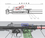
Another info that can be derived from these diagrams (even though they're not mentioned in the document) is that the 191 has a spring loaded lever (circled in red) that keeps the cam pin from rubbing against the cam track during the closing stroke of the bolt carrier. Basically, this lever keeps the bolt in the unlocked position until the bolt reaches the front-most position, where a metal piece in the receiver (circled in blue) depresses the lever, allowing the bolt to lock.
1642209810249.png
 

Kejora

Junior Member
Registered Member
I believe the full document that contains those diagrams describes a retaining mechanism for the firing pin. If you know the AR15, it has an elastic cotter pin going across the bolt carrier to keep the firing pin from sliding out the back. The document states that this piece on the AR15 can loose its elasticity and fall out over time. So a new mechanism was proposed, where another spring loaded plunger will keep that firing pin retaining pin in place, and you will need to use a punch to remove it. I think we can assume that this mechanism is intended to be applied to the 191 family, but since it's only a patent document, we can't determine if it's actually implemented without seeing a photo of a physical bolt carrier group.

Another info that can be derived from these diagrams (even though they're not mentioned in the document) is that the 191 has a spring loaded lever (circled in red) that keeps the cam pin from rubbing against the cam track during the closing stroke of the bolt carrier. Basically, this lever keeps the bolt in the unlocked position until the bolt reaches the front-most position, where a metal piece in the receiver (circled in blue) depresses the lever, allowing the bolt to lock.
View attachment 81232
 

Dylan Nguyen

Junior Member
Registered Member
Something I haven’t seen many people talk about on this forum is the unique dual-port and dual-chamber gas block design of the QBZ-191. I can’t think of any other rifle with two gas ports or a gas block with dual chambers like the one found on the QBZ-191. The design, according to the patent, is supposed to improve reliability.
 

Attachments

  • 2505DAF8-5ABC-4E27-BD11-03406AED6CE2.jpeg
    2505DAF8-5ABC-4E27-BD11-03406AED6CE2.jpeg
    99.8 KB · Views: 43

enroger

Junior Member
Registered Member
Something I haven’t seen many people talk about on this forum is the unique dual-port and dual-chamber gas block design of the QBZ-191. I can’t think of any other rifle with two gas ports or a gas block with dual chambers like the one found on the QBZ-191. The design, according to the patent, is supposed to improve reliability.

Interesting. I'm not a gun person, anyone can explain how this improves reliability?
 

Cabbage

Just Hatched
Registered Member
I believe we have two dual-chamber gas block designs:

1. Dual-chamber, single-port (Patent number CN107328299A, applied 2017-08-18):
1642258887015.png
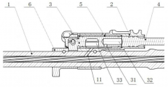
Gas first enters through port [11], then expands in chamber [33]. This expansion allows the pressure and temperature of the gas to drop. After that, the gas travels to port [31] and enters chamber [32], where it acts on the piston and cycles the gun. The reduced pressure means that gas port erosion happens more slowly, which increases the life of the regulator. This is a perk in reliability because an eroded gas port would allow an excessive amount of gases to reach the piston, which cycles the gun faster and more violently.

2. Dual-chamber, dual-port (Patent number CN207132773U, applied 2017-09-08):
1642258902396.png
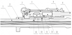
The difference between this and the previous design is the addition of a perpendicular gas port (port [11]). In this design, gas first enters through the smaller port [11], then expands into both chamber [32] and [33]. The pressure and temperature is reduced during this expansion. This initial amount of gas provides a “soft start” to the piston, but is probably insufficient to fully cycle the gun. Next, as the bullet passes the bigger port [12], an additional amount of gas travels up this port, expands into chamber [33], pressure and temperature are reduced. Then it travels to chamber [32] and provide the remaining amount of force needed to cycle the action fully.

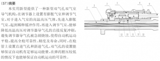
In the patent document, the dual-chamber dual-port design is stated as having more kinetic energy to cycle the gun in cases where the ammunition has lower pressure:
1642258948644.png
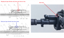
This is only my speculation, but the fact that these two patents are applied so close together leads me to believe that they wanted the dual-port design to be a backup to the single-port design, in case the gas pressure drops too much in the single port that it can’t reliably cycle the gun. I’m also fairly certain that only the single-port design was adopted, since I have never seen a gun with two holes on top of the gas block.
1642258934087.png
Also keep in mind that I don’t speek Chinese and used google translate, so if you do, you can verify if I interpreted the documents correctly:
Please, Log in or Register to view URLs content!

Please, Log in or Register to view URLs content!
 

Cabbage

Just Hatched
Registered Member
Dual oblique extractor springs – Patent number CN210533167U – Applied 2019-09-30
Please, Log in or Register to view URLs content!


This patent states that on traditional AR15 designs, the single extractor spring placed perpendicular to the bolt has a few disadvantages. First, it’s length is limited by the fact that there is a firing pin channel right beneath. This limit in length limits the force that this spring can generate. Second, the traditional AR extractor spring only puts tension on the extractor in the radial direction (i.e., perpendicular to the axis of the bolt). This means that the extractor still has “slop” in the axial direction, where it is allowed to slide back and forth along the length of the bolt a miniscule amount due to the tolerances between parts. This leads to inconsistent ejection. However, the patent also recognizes the benefit of AR extractor designs in that it allows the bolt head to be very small in diameter, leading to a more compact weapon, as opposed to AK extractors that require a large bolt head.
1642320268399.png
Below are the diagrams of the dual oblique extractor springs proposed in the patent:
1642320334737.png
The benefits stated in the patent are:
  • Two extractor springs provide a stronger clamping force, leading to better engagement of the extractor on the cartridge rim.
  • They don’t interfere with the firing pin channel, so they can be much longer
  • The oblique orientation of the extractor springs put forces on the extractor in both the radial and axial direction, effectively eliminating all slop, leading to more consistent ejection.
Additional information that can be inferred from this patent: The bolt head is AR-style, but with only 4 locking lugs. The lengths of the locking lugs (in the axial direction) are not uniform, for unknown reasons. There is also no plunger ejector, so the ejector is fixed. This conclusion can also be supported by the fact that there is a visible slot on the bolt & bolt carrier in the diagram below, taken from one of the other patents posted earlier in this thread (patent CN111426234A):
1642320370161.png
The usual disclaimer applies: these are only patent drawings so there are no guarantees that these features are applied to the actual guns identically to how they’re drawn here. However I am more sure about some features than others. The 4-lug bolt looks pretty reasonable, since the orientation of the top bolt lug matches what can be seen in the following screenshot:
1642320391246.png
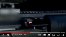
The fixed ejector is also a fair assumption, due to the ejection pattern and what looks like two rivets on the left side to mount a fixed ejector to the upper:
1642320451206.png
Currently I don’t think there is any media that confirms the implementation of the dual oblique ejector springs.
 

Dylan Nguyen

Junior Member
Registered Member
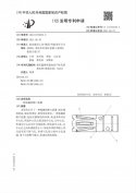
Patent CN113310345A: The Muzzle Device of QBZ-191
Patent application filed 2021-06-29 by Chongqing Jianshe Industry Group Co Ltd

7A59068E-7148-408F-AB47-74B18AF532DB.jpegD2F69D76-9437-42B7-ADDC-3A5E50127AAE.jpeg27C0B8FF-4C27-42B1-B821-4AAE0C79835D.jpeg

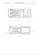
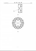
This is muzzle device of QBZ-191. According to the patent, the 6-port design of this device is meant to reduce the recoil of the weapon and thus increase the accuracy. I have to disagree with this though. This design is more akin to a flash hider like the A2 flash hider found on many AR-15/M16 weapons, and does not have any of the characteristics found on compensators or other muzzle devices that do reduce recoil.

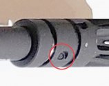
Another interesting thing I found was that the device does not thread on to the barrel of QBZ-191. Instead, it pins on. According to the patent, this method of attaching the device to the barrel ensures a more secure attachment. Whether or not this is true, I am unsure.

This also means that the barrel of QBZ-191 is not threaded.

We can see one of the pins here:
51B26DFF-1B6D-49A8-AC3A-AAF9A08CD5A1.jpeg

Lastly, this device has a built-in quick detach feature which allows the quick installation of suppressors, bayonets, grenades, and blank adapters over the muzzle device.
 
Top