PLAN Catapult Development Thread, News, etc.

taxiya

Brigadier
Registered Member
Thank you Max for that paper, something interesting to study.

I think you may have mixed the energy with power in case of EMALS, or you mixed the two issues. It deliver 484MJ in 3s, but takes 45s to store that 484MJ from the power grid. The arresting takes few seconds, almost equivalent to the launching. It is the speed of recharging the launcher that makes it a use case, of course that is assuming we are launching and recovering at the same time (aircraft have to rearm, refuel and launch again). This is valuable for both conventional and nuclear CV although I don't know if that scenario is necessary or doable in real combat. For nuclear CV, the recovery of the energy is not necessary.

Before reading the paper, I can say that AC has its own complicity no less than DC, but in different areas. AC is easy to cut off in case some power surge because it has zero point, but it is very difficult to keep frequency and phase sync, the control system would be much more complicated than DC therefor costly. DC's problem is sensing the surge in extreme short time and cut a high current. Prof. Ma has an algorithm with prediction to sense and cut, which is one of the challenges he talked about. Another thing is cutting the current by high power semi-conductor which was expensive some years ago, but not these days. DC high power grid is not more expensive as 10 years ago thanks to the recent fast tech advancement in wind power application, improvement in semi-conductors, and building of national UHVDC network which I think China is the biggest user.

I also want to say that, the presumption of AC IEPS being cheaper is both right and wrong. At the time of its development some decades ago, DC power devices were either expensive or non existence, so it is right to say AC is cheaper because it seemed more realistic. But the presumption overlooked the complicity of the control system, or underestimated it, therefor missed that extra cost. Take Type 45 for example, all ships will have to be added with an extra diesel generator, and even that is just a patchwork that does not address the root cause. I am afraid that solving that root cause will be too expensive for UK, and better to move to DC if they can and have the budget. As for USN, I guess the next IEPS will have to be DC based, be it CV or destroyer.
 

Zool

Junior Member
I would imagine the system would act similar to a VFD, or a multitude of VFDs. AC power straight from the turbine generators and into some kind of distributed system. With AC you can step up or down with a transformer and AC unlike DC provides frequency control, so you have fine adjustment to overall power output as needed. I work with FANUC Robotics and a variety of VFD setups in industry and that's been my experience anyway (starting with AC bringing the most flexibility to your system).
 

Max Demian

Junior Member
Registered Member
@taxiya

What is the bottleneck in the 45s charging of the flywheel? The input power, or an artifact of the energy conversion mechanism? I saw some figures of 120MW electrical power for the Ford carrier, in addition to 260MW for the propulsion.

To be clear, I am not an electrical nor mechanical engineer. My reading of Doerry's papers was that MVDC architecture's biggest benefit is increased power density. This is in part because they allow generators to run at high frequencies which improves power density. DC networked ships also allow for acoustic signature improvement (running your gear at high freqs), which could be of great benefit to some platforms. There is also the potential of using less bulky cabling.

While DC networks inherently decouple prime mover speed from power quality, an AC network could achieve the same at the cost of adding a sufficiently sized energy storage device, at least that's what I understood.

The US appears to have adopted an incremental approach to IPS, with current platforms (LHD-8, America class and Zumwalt class) employing a MVAC network (with Burke Flight III to come). It's curious to point out that the Zumwalt class uses a 1000 VDC power distribution network, where the main trunk of the network is MVAC.
 
Last edited:

taxiya

Brigadier
Registered Member
@taxiya

What is the bottleneck in the 45s charging of the flywheel? The input power, or an artifact of the energy conversion mechanism? I saw some figures of 120MW electrical power for the Ford carrier, in addition to 260MW for the propulsion.

To be clear, I am not an electrical nor mechanical engineer. My reading of Doerry's papers was that MVDC architecture's biggest benefit is increased power density. This is in part because they allow generators to run at high frequencies which improves power density. DC networked ships also allow for acoustic signature improvement (running your gear at high freqs), which could be of great benefit to some platforms. There is also the potential of using less bulky cabling.

While DC networks inherently decouple prime mover speed from power quality, an AC network could achieve the same at the cost of adding a sufficiently sized energy storage device, at least that's what I understood.

The US appears to have adopted an incremental approach to IPS, with current platforms (LHD-8, America class and Zumwalt class) employing a MVAC network (with Burke Flight III to come). It's curious to point out that the Zumwalt class uses a 1000 VDC power distribution network, where the main trunk of the network is MVAC.

The bottleneck is flywheel, to spin up it takes long time because of the inertia. One the one hand, less mess lead to less inertia, faster charging. On the other hand, less mess means less energy stored at the same RPM. It is an inherited character of flywheel. It is a bottleneck both for recharging and releasing during launch. Translated to a low power density. Flywheel has high energy density though. This is demonstrated in EMALS where four (?) flywheels are combined to one launching rail, at the end of a launch each flywheel still has about 75% of energy stored because it can not release 100% energy in 3s.

I think you may misunderstood the paper. MVDC is just about the grid and the overall architecture, the storage system can be anything including flywheel just like in an AC system. Flywheel has the highest energy density so far, with chemical battery comes second. Super capacity has the highest power density but least energy density meaning it is bulkier to save the same amount of energy. It is true that DC grid allow generators to run at any frequency, it improves flexibility and feasibility which enables measures such as recovering otherwise wasted energy during a given time, which is translated to power density. It is a derived effect, not a direct effect. Less bulky cabling is one advantage of MVDC mentioned by Prof. Ma as well. Just remember, HFAC also reduces cabling bulk.

You are right, integrating storage to smooth out the power quality is a wildly used method not only in IEPS, but in general power grid. Problem is the extra cost and extra bulk, and most importantly the extra complexity of control. Once again, Type 45 is a "good" lesson to learn, it does not have that storage, even if it has it would mean similar bulk as the to-be-added diesel generator.

As to the approach, US and UK were NOT wrong to develop MVAC some decades ago when DC is almost impossible. According to Prof. Ma's paper, US has had MVDC in their roadmap long time ago. China has the new-comer's advantage, by the time when it begin IEPS work, DC components and experiences are abundant enough to make MVAC obsolete. So that "incremental" is unnecessary to China, but was necessary to US. HOWEVER, as an armchair general, I would not have gone into MVAC if I were USN. From what we have seen today, it is a dead end. But again, there is no guarantee that people back then could have foreseen all problems when development progressed.

One extra thing, besides CV recovering energy from arresting aircraft, other ships can and must recover energy from a free running electrical motor decoupled from the propeller in case of sudden deceleration or turn. Without doing so, the free turning motor becomes a generator of decreasing frequency feeding electricity back to the grid creating surge due to out of sync current, that burns the grid, I am sure that Type 45 suffered this multiple times. It is not just the "intercooler in hot sea" to blame, the breakdowns in mid Atlantic have to have some other reasons.

Where did you read that Zumwalt class use 1000VDC connected to MVAC trunk? Can you give me the link and quote the part? Remember, AC induction motor need the capability to change RPM for propelling speed. It works by "grid AC -> DC -> variable frequency AC = variable RPM". AC induction motor's RPM is locked to the AC frequency input, to spin up or down the input frequency has to be changed. The grid frequency has to remain constant, so the only way is to convert to DC first, then use semi-conductors to create desired AC frequency. The device is called Variable-frequency Drive (VFD). Zumwalt may use 1000VDC in its VFD, but that is not the DC grid we are talking about. In a MVDC or any IEPS, so long as we use induction motor, that AC-DC-AC conversion always remains.
 
Last edited:

Max Demian

Junior Member
Registered Member
Where did you read that Zumwalt class use 1000VDC connected to MVAC trunk? Can you give me the link and quote the part?

I read it from this article, again by Doerry:
Please, Log in or Register to view URLs content!


Quote: "Zumwalt re-introduces d.c. power to naval surface combatants. As part of the Integrated Fight Through Power (IFTP) system, Zumwalt employs a 1000 V d.c. distribution system. Additionally, Zumwalt incorporates 375 V d.c. and 650 V d.c load interfaces ... "

IFTP on the Zumwalt is an implementation of ZED (zonal energy distribution).

I googled a bit more about this, and found this master thesis:
Please, Log in or Register to view URLs content!

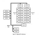
Therein, Figure 10 presents a speculation of Zumwalt's power grid architecture with the main MVAC bus connected to the four generator sets and driving the two AIMs, while also being connected to 3 power conversion modules (PCM-4) that bridge over to the 1000 VDC bus.
 

taxiya

Brigadier
Registered Member
I read it from this article, again by Doerry:
Please, Log in or Register to view URLs content!


Quote: "Zumwalt re-introduces d.c. power to naval surface combatants. As part of the Integrated Fight Through Power (IFTP) system, Zumwalt employs a 1000 V d.c. distribution system. Additionally, Zumwalt incorporates 375 V d.c. and 650 V d.c load interfaces ... "

IFTP on the Zumwalt is an implementation of ZED (zonal energy distribution).

I googled a bit more about this, and found this master thesis:
Please, Log in or Register to view URLs content!

Therein, Figure 10 presents a speculation of Zumwalt's power grid architecture with the main MVAC bus connected to the four generator sets and driving the two AIMs, while also being connected to 3 power conversion modules (PCM-4) that bridge over to the 1000 VDC bus.
Alright, 1000VDC is the bus for everything except the propulsion.

PCM "Power Conversion Module", transformer and rectifier.
PMM "Propulsion Motor Module".
Without any other consumer in the diagram, I assume that most if not all electronics on the ship are hooked to DC bus, about 10 to 20 % of total load, the propulsion takes the rest. This solution does improve the condition for electronics like radar etc, it can not handle the problem I talked about, the power surge and disturbance of the propulsion system. Zumwalt potentially has the same issue as Type-45 which will manifest sooner or later. Therefor, my prediction of next USN IEPS ship won't use the same architecture of Zumwalt.

Worth to note, one may ask about QE-II class CV which use AC based IEPS too. I'd say the "thing" is there, but much less likely to manifest because as a CV because she will never accelerate or decelerate as crazy as a destroyer. QE-II is more like a civilian ground-based powerplant.
upload_2019-8-4_1-13-9.png
 
Last edited:

Max Demian

Junior Member
Registered Member
Worth to note, one may ask about QE-II class CV which use AC based IEPS too. I'd say the "thing" is there, but much less likely to manifest because as a CV because she will never accelerate or decelerate as crazy as a destroyer. QE-II is more like a civilian ground-based powerplant.
View attachment 53199

They still need to be capable of executing tight turns during evasive maneuvers. In light of all that's being said, I find it illustrative to observe that the Ford class does not adopt IEPS. The propulsion system appears to retain the proven steam-mechanical drive and keep it decoupled from the ship electric grid.
 

Max Demian

Junior Member
Registered Member
One extra thing, besides CV recovering energy from arresting aircraft, other ships can and must recover energy from a free running electrical motor decoupled from the propeller in case of sudden deceleration or turn. Without doing so, the free turning motor becomes a generator of decreasing frequency feeding electricity back to the grid creating surge due to out of sync current, that burns the grid, I am sure that Type 45 suffered this multiple times. It is not just the "intercooler in hot sea" to blame, the breakdowns in mid Atlantic have to have some other reasons.
I was re-reading what you wrote here and tried to connect it with the problems the Type 45 is experiencing and the solution of adding a third diesel generator to the ship grid.

What I fail to understand is how does the third generator help with the problem that you described? Or does it even?

It seems rather to be the solution to the sudden and complete failure of the main GTs , whereafter the auxilary diesel generator is unable to cope with the extant electric load and trips out? This looks like a bad QOS design which is unable to quickly respond and shed excessive loads. A scenario like this was described in the Moerry paper I linked.
 

taxiya

Brigadier
Registered Member
I was re-reading what you wrote here and tried to connect it with the problems the Type 45 is experiencing and the solution of adding a third diesel generator to the ship grid.

What I fail to understand is how does the third generator help with the problem that you described? Or does it even?

It seems rather to be the solution to the sudden and complete failure of the main GTs , whereafter the auxilary diesel generator is unable to cope with the extant electric load and trips out? This looks like a bad QOS design which is unable to quickly respond and shed excessive loads. A scenario like this was described in the Moerry paper I linked.

There are more than one problems that Type 45 is facing.

No, the extra diesel generator does not fully address the problem that I described, that is the sudden lose of GT output leading to instability of frequency. But it does partially address the problem by not reducing the power demand from the GT in the form of increasing the power margin. That is to reduce the load demand from GT, letting it to run at much lower power rating. This lower rating means that even if the intercooler failed, the GT is still able to provide enough power in the mode of simple-cycle.
 

taxiya

Brigadier
Registered Member
They still need to be capable of executing tight turns during evasive maneuvers. In light of all that's being said, I find it illustrative to observe that the Ford class does not adopt IEPS. The propulsion system appears to retain the proven steam-mechanical drive and keep it decoupled from the ship electric grid.
Just remember, in a tight turn the motors are still running at full power. So long as the motor's power consumption does not drastically change, it will be fine.
I agree that Ford class is more practical and realistic approach before USN has mastered MVDC.
 
Top