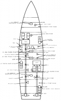
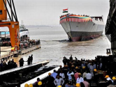
You are making things up now. Look at the Type 003 under construction and how far away the MERs are spaced. That is with the intent purpose for the ship to weather blast/flooding damage in that compartment and at the very least keep on steaming if not fighting. A ship dead in the water is a major liability. If the threat environment is unfavorable, they typically end up scuttled by their own side.
Even the Type 055 has a compartment of separation between its MERs. That's evidence that they do care about battle damage.
Smokestack separation correlates with MER separation. Sometimes, if volume is available, additional ducting can be used to increase separation. Based on diagrams published by CCTV, they don't seem to have increased the separation by much if at all compared to the smokestacks:
View attachment 70197
View attachment 70196
Okay, so first of all, your original argument should never have been about the funnels to begin with, but the prime movers or MERs.
I'm not sure why you were so focused on the funnels in post #419, when the actual point of your argument is about the position of the prime movers. Why bother using the funnels as a proxy.
As for the positioning of the prime movers themselves, it's not quite so simple as you describe.
The ideal ship to maximize survivability of its prime movers and immediate adjacent gear boxes would ideally have them spaced far away from each other, duplicating redundancy as well.
But that adds complexity, weight, and is limited by the geometry of your ship.
It also limits the kind of gearing that your ship can accommodate.
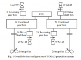
In the case of 055, it is basically confirmed that it adopts a combined connector gear COGAG system, which basically allows one single gas turbine to run at full efficiency to propel both shafts -- or up to all four to propel both shafts.

Compare that to say, the Spruance/Tico (depicted below) or Burke family, where each shaft is only connected to two of each of the four gas turbines. Not as big of a problem if you're running all four turbines at full speed, but it becomes an issue if you want to cruise more economically, meaning you are forced to run a single gas turbine to turn a single shaft, while the other shaft is actually left unpowered to just turn in the current.

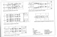
And then of course there are a whole heap of weird and wonderful arrangements of prime movers and gear boxes and shafts depending on type:

And one can find quite a few good 3D depictions of their setups in certain promotional material, such as here, including for various naval ships like F125, FREMM, NSC:
..... All this is to say, it isn't quite a simple as "bad design because prime movers all located close together" -- but it was likely a deliberate and informed choice to balance the requirements of survivability and the output, efficiency and reliability of their propulsion configuration, as well as in relation to the overall kind of damage they assess to be likely, and the other tradeoffs in terms of placement of weapons, sensors etc.
E.g. if we were only to consider the propulsion configuration alone: if the PLAN had chosen to space out the prime movers of 055 in a manner similar to Spruance/Tico class, would they have been able to install a combined connector gear system? What is their assessment of likely damage to the propulsion system -- e.g.: flooding versus direct damage to the prime movers versus breaking of the shaft? Would spacing of the prime movers been able to enable them to put in six auxiliary generators for service power in the way they did on the 055? etc
I don't think we have the ability to divine the answers to those questions to reach a sensible conclusion.
If you wanted to have a discussion about comparative design trade offs for various propulsion configurations and to evaluate 055's configuration, I don't think anyone would have had an issue with that.
But the way you wrote post #419 is oversimplistic and overreaches.
Last edited:

