Some of the activities TRMotor is conducting
Design and Development
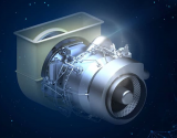
With our ever-expanding team and strong expert engineers, a number of projects are being carried out simultaneously for the power systems of the platforms needed in our country. In addition to the design and development studies of aviation gas turbine engines ranging from conceptual design to detail design, the necessary infrastructure for prototype manufacturing and product testing activities is also successfully created.
SUBSYSTEMS
TRMOTOR carries out the system level design of subsystems for turbofan engines and auxiliary power units and manages the product development processes of the relevant equipment. These subsystems include gearbox, lubrication, fuel, pneumatics, hydraulics, ignition, electrical and electronic control systems.
Hydraulic Activation Systems
The systems that provide mobility to the IGV, VSV and nozzle mechanisms at the rear of the engine used in gas turbine engines have been developed with an integrated design into the engine. These systems allow to activate these blades with the help of hydraulic fluid. In addition, the hydraulic power unit planned to be used in the engine; It includes components such as hydraulic pump, tank, filters, relief valves, check valve, bypass valve, electro hydraulic servo valves. This comprehensive system activates the actuators and ensures that the blades are positioned in the appropriate position.
TRMOTOR carries out its work in this field with high precision and expertise and focuses on the design and development of subsystems in gas turbine engines. With its superior engineering knowledge and experience, TRMOTOR aims to raise quality standards in the aviation industry and contributes to progress in this field with innovation.
Fuel System
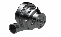
In gas turbine engines, the fuel system basically consists of a series of components that transport fuel to the combustion chamber inside the engine. Among these components, fuel pumps, fuel filter, fuel control unit and control valves are of the highest importance. Fuel pumps are responsible for properly delivering fuel to the combustion chamber under different flight conditions. Fuel control valves regulate fuel flow and control engine performance. Fuel filters support the efficient operation of the engine by cleaning the fuel. All these components form the cornerstones of the fuel system to ensure the safe and reliable operation of gas turbine engines.
TRMOTOR carries out its work in this critical field of the aviation industry with great dedication and expertise. Our company assumes a leading role in the industry by combining advanced technology with its experienced engineering staff in the design, development and integration of fuel system components. It aims to ensure the efficient operation of fuel systems and the reliability of the aviation industry by adhering to high quality standards and safety principles.
Lubrication System
In gas turbine engines, the lubrication system lubricates rotor bearings and gears; cooling of bearings, carbon seals and turbine areas; It ensures the removal of foreign substances in the crankcase area and the dampening of dynamic loads in the bearing areas. The tank, heat exchangers, filters, valves and pumps in the system ensure the safe and reliable operation of the engines.
TRMOTOR continues its work by considering the critical role of lubrication systems in the aviation industry from a priority perspective. Our expert engineers make significant contributions to the design and development of lubrication systems and focus on raising industry standards. Lubrication systems are the guarantee of efficient and safe operation of engines. TRMOTOR continues to contribute to the aviation industry with its work in this field.
MATERIAL TECHNOLOGIES
Our company carries out material and process studies in order to design and produce our country's unique aviation engines in a way that meets the necessary requirements. In this context, activities such as determining the material properties required for design, creating material databases, supporting characterization, material and process selection processes, material development, process development and application, creating relevant specifications, process improvement and creating innovative material-process technology projects are carried out. .
Material Development Projects
The materials used in aircraft engines are generally aluminum alloys, steel alloys, titanium alloys and superalloys. These are alloys that can withstand challenging environmental conditions, where the number of producers in the world is small and export restrictions are applied. TRMOTOR carries out alloy development projects for this purpose. Necessary collaborations are realized to ensure maximum use of the infrastructures in our country in development projects.
Production and Assembly
TRMOTOR, by prioritizing customers' trust and satisfaction, offers comprehensive services in the field of aircraft engines, auxiliary power units (APUs) and subsystems. It aims to contribute to the aviation industry with its advanced technology, experienced team and quality-oriented approach.
Prototype and Mass Production
In order to meet customer needs and provide high quality products, auxiliary power units (APU), subsystems and gas turbine engines are produced in modern production facilities. TRMOTOR uses innovative techniques when carrying out manufacturing projects and adopts quality control processes in accordance with aviation standards.
Assembly
TRMOTOR aims to successfully carry out precision assembly operations of aircraft engines in its modern facilities with its experienced teams. It offers customers high-performance products thanks to its commitment to innovative technologies and safety standards. In this context, it is planned to meticulously complete the assembly activities of auxiliary power units (APU), subsystems and gas turbine engines within TRMOTOR.
Testing Activities
Following the design and production processes, aircraft engines and APU systems are subjected to extensive testing. These tests ensure performance, safety and durability. For this purpose, TRMOTOR has different test system capabilities at the engine and subsystem level.
Testing Capabilities
Engine assembly development units.
Flow laboratory.
ATS test rig.
Hydraulic & pneumatic test benches.
Electronic systems test bench.
Lubrication system test bench.
Fuel system test bench.
Accessory gearbox test bench.

 ). So we're basically limited to first principles and generalizations to establish upper boundaries here.
