KJ-600 carrierborne AEWC thread

Blitzo

Lieutenant General
Staff member
Super Moderator
Registered Member
By analogy based on shared features/influence from KJ-2000 and KJ-500. Of course, that’s not definitive.

Being developed from experience and technology gained from past AEW&C projects doesn't mean that it will literally adopt the same configuration.

Phased array radars can be arranged in a manner where multiple arrays are fixed and provide 360 degree coverage or they can be mounted on a mechnical rotating platform.


APY-9 is not an AESA. It is mechanically rotated PESA radar.

On what basis do you say that.


OK. I wasn’t aware of that.

Well, we've had strong hints for a while that it would likely have a mechanically scanned rotadome configuration, and the idea that they would stick anything other than an AESA in there is very unlikely. By process of elimination, a mechanically scanned rotadome w/ AESA should easily be the most obvious solution, and is a proven configuration on other AEW&C aircraft like E-2D or C-295 AEWC as well.
 

Max Demian

Junior Member
Registered Member
Being developed from experience and technology gained from past AEW&C projects doesn't mean that it will literally adopt the same configuration.

Phased array radars can be arranged in a manner where multiple arrays are fixed and provide 360 degree coverage or they can be mounted on a mechnical rotating platform.
Adopting a single rotating antenna is a big departure from KJ-2000 and KJ-500. If that's true, then I would not expect all that much commonality between the systems. On the other hand, both E-3 and E-2 use a single rotating antenna design (except that E-3 uses a rotodome).

On what basis do you say that.

Based on several articles from USNI and Flightglobal.

This part from Flightglobal about the need for mechanical scanning:
"Although mechanically scanned arrays are growing obsolete, technology does not yet exist for a UHF-band (300MHz to 1GHz) electronically scanned array (UESA) to fit within the size and weight limits aboard the Hawkeye airframe. At the time Northrop launched the programme, it was reported that a UESA system would require 27 transmit modules to achieve 360e_SDgr coverage.
... the 18-channel Lockheed Martin APY-9 electronically scanned array scans for airborne objects across an arc up to 90e_SDgr wide.
"

From USNI:
"Further, the 18-channel passive phased-array ADS-18 antenna has the ability to steer its radar beam electronically. It also incorporates an electronically-scanned identification friend or foe system.

The transmitter and receiver hardware are located inside the aircraft’s fuselage and connect to the antenna via high power radiofrequency transmission lines and a high power radiofrequency rotary coupler. Thus, it is not an active electronically scanned array radar."


Source:
Please, Log in or Register to view URLs content!


Well, we've had strong hints for a while that it would likely have a mechanically scanned rotadome configuration, and the idea that they would stick anything other than an AESA in there is very unlikely. By process of elimination, a mechanically scanned rotadome w/ AESA should easily be the most obvious solution, and is a proven configuration on other AEW&C aircraft like E-2D or C-295 AEWC as well.
I don't think it's that simple. Each design is specific with its unique set of constraints and trade-offs.
 

Tam

Brigadier
Registered Member
By analogy, AESA would imply a non-rotating dome.

Interesting divergence in approach. The US favors a larger single antenna in a rotating dome, over 3 smaller 120d view AESAs.

What has me really intrigued is why the US is still using a PESA architecture for APY-9 on E-2D, even though the radar is fully digital with a solid state transmitter and receiver. My hunch is that it has to do with weight/CG/momentum and cooling, which is easier to deal with in a PESA design.

Sorry for digressing.

Certainly won't be about weight, as PESA tends to weigh more. A rotating mass with gyroscopic effects isn't good for CG and momentum/ Cooling should not be an issue with AESA since you should get ventilated by the airflow of the plane going forward, while the airflow you get from a rotating disk is neglible.

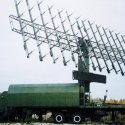
PLAAF_Shaanxi_Y-8_-_KJ200.jpg


The reason why it turns around is that the array is UHF. The wavelength is so long, it can only consist of a few elements set in a line. It won't matter if the array is an AESA or a PESA. It is really an array of Yagis, 8 elements on each side. If you like something similar in concept try the Type 517M radar on the 052D.

kNruqbr.jpg

From a space perspective, a PESA with a single transmitter for all is probably most efficient in space. Being UHF, and keeping in mind the space needed between each element, you need the most cross section area of the disk as possible so the array needs to be at the center of the disk. To steer electronically, and this will only go sideways, the phase shift would have to be a delay in the transmit, so some elements would be sequentially delayed, and that causes the beam to steer. But with only one side, to get a full 360 degrees you need to rotate it.

The artwork --- not official --- regarding the KJ-600 tends to portray this delta that points to an AESA (or PESA) with three sides.

Egy6ieDWkAEzzyu.jpg


This image below however, suggests a dual sided array. Compared to how small the cross section area of the array is available if you do a triangular configuration vs. a dual sided, a triple sided would not allow as many elements as you have with a dual side if you are using UHF. You probably have to go down to L-band which will greatly increase the number of elements and offer greater angular resolution, but UHF is going to be more stealth proof.

Fuzzy image on the KJ-600 prototype suggests a single or dual sided disk if the coloring is of any indication.

kj-600.jpg
 
Last edited:

Max Demian

Junior Member
Registered Member
Certainly won't be about weight, as PESA tends to weigh more. A rotating mass with gyroscopic effects isn't good for CG and momentum/ Cooling should not be an issue with AESA since you should get ventilated by the airflow of the plane going forward, while the airflow you get from a rotating disk is negligible.
An AESA would have much more weight in the radome. It has to colocate the transmitter (s) and cooling within the antenna. Whether you go air cooling or liquid cooling, depends on the power output. E-2D adopted liquid cooling for its solid state transmitter.

Edit:
For balance you need to have back to back arrays.
Why? AFAIK, the other side of the radome of E-2D contains ESM instruments.
 
Last edited:

Tam

Brigadier
Registered Member
Here is some more information I dug up.

images (5).jpeg

The mock up on the 003 mock up has two faint lines across the radome. This points to either a single or dual sided array.

There is something called the KLC-7, aka Silk Road Eye. It does not have the triangular formation like on the KJ-500.


D4zV6fNWAAA1jRS.jpg


KLC-7a.jpg


There is also something called the ZDK-03.

ZDK-03_radar.jpg
 

Tam

Brigadier
Registered Member
An AESA would have much more weight in the radome. It has to colocate the transmitter (s) and cooling within the antenna. Whether you go air cooling or liquid cooling, depends on the power output. E-2D adopted liquid cooling for its solid state transmitter.

AESA transmitters have negligible weight. They are only tiny ICs. Cooling? Air cooled is more than enough. For a UHF you only are going to have eight transmitter elements. Even if you are an L-band, you are not going to feature that many elements, compared to say, a highly dense X-band radar. That also leaves you with plenty of spacing between them.

Edit:

Why? AFAIK, the other side of the radome of E-2D contains ESM instruments.

ESM would require an antenna or antennas as a receiver. Its passive or receive only radar. If weight on a rotating disk is not equal, it will wobble. You need to artificially balance the weight distribution of the disk.
 

Max Demian

Junior Member
Registered Member
AESA transmitters have negligible weight. They are only tiny ICs. Cooling? Air cooled is more than enough.
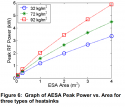
Now you are just hand-waving. Would be much better if you could provide actual weight figures for UHF T/Rs (including the heatsinks). Here is a power vs weight figure for a C-band air-cooled AESA:
aesa_weight.png
A 3m2 array with 3.5kW peak power would weigh 270kg. Liquid cooling would be needed to bring the weight further down.

A PESA design would not require the bulky heatsink to be installed in the rotating radome. This is a significant difference.

For a UHF you only are going to have eight transmitter elements. Even if you are an L-band, you are not going to feature that many elements, compared to say, a highly dense X-band radar. That also leaves you with plenty of spacing between them.
The APY-9 is quoted with 18 channels, so I assume that would be 18 T/R if AESA. The cutaway diagram shows a 18 channel rotary RF coupler.

Looking at this from another angle, an argument for PESA could be insufficient power of AESA design with only 18 space and weight constrained T/R vs one large transmitter in the fuselage of the aircraft. In the cutaway illustration you posted, E44 and E46 designate the receiver/exciter and transmitter, in the compartment behind the cockpit.
 
Last edited:

Tam

Brigadier
Registered Member
Now you are just hand-waving. Would be much better if you could provide actual weight figures for UHF T/Rs (including the heatsinks). Here is a power vs weight figure for a C-band air-cooled AESA:
View attachment 63105
A 3m2 array with 3.5kW peak power would weigh 270kg. Liquid cooling would be needed to bring the weight further down.

Can you show me the link to that graph? I want to see the context of it before it was taken out of.

A PESA design would not require the bulky heatsink to be installed in the rotating radome. This is a significant difference.

This AESA here uses air cooling. So does this. I don't see how a bulky heat sink can be used here.

Y-8WKJ-200 CubHigh New 5 KJ-200 or 'Y-8 Balanced Beam PLA-AF Airborne Early Warning & Control ...jpgmain-qimg-a20b90731ce0a9d989189b6e3e6b0ca9.jpeg

See the inlet on the front of the array designed to take in air.

The APY-9 is quoted with 18 channels, so I assume that would be 18 T/R if AESA. The cutaway diagram shows a 18 channel rotary RF coupler.

I see nine guides that makes up the separators and frame for the dome. 9 TR might be for the main radar itself, the other 9 might be for the IFF.

That all depends on the frequency used, which end of the UHF band the radar is using, is it on the meter length side or the short decimeter side.

Looking at this from another angle, an argument for PESA could be insufficient power of AESA design with only 18 space and weight constrained T/R vs one large transmitter in the fuselage of the aircraft. In the cutaway illustration you posted, E44 and E46 designate the receiver/exciter and transmitter, in the compartment behind the cockpit.

I am not sure how the AESA design would be of insufficient power when you can simply scale up to have each element have a more powerful transmitter.

A single transmitter would actually be more challenging to cool than say 18 separate transmitters because being of a concentrated heat source rather than 18 separate ones that are more easily distributed and with more surface area between these transmitters.

If you have a power amp inside an AESA module, it would look like this.

QPM1002.jpg

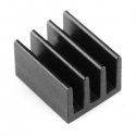
Like any IC that would require a heat sink that's attached to the chip itself with a thermal conducting compound.

10746-02a.jpg
 
Last edited:

Max Demian

Junior Member
Registered Member
Can you show me the link to that graph? I want to see the context of it before it was taken out of.
This is the source: An airborne phased array radar concept for atmospheric research, Eric Loew et al


This AESA here uses air cooling. So does this. I don't see how a bulky heat sink can be used here.

View attachment 63106View attachment 63107

See the inlet on the front of the array designed to take in air.
The heatsink is inside, we just don't see it. There's no other way to take away the heat. The radars on those planes are suspended on both sides and do not rotate. That should make it easier to handle a large load.

But without knowing the output power, it is impossible to make comparisons. My 40g Intel CPU has a 1.3kg heatsink dual fan setup sitting over it. I could've stayed with the stock heatsink weighing 10 times less, but then I wouldn't be able to overclock and the operating temperatures would've been way higher at the same settings.


I see nine guides that makes up the separators and frame for the dome. 9 TR might be for the main radar itself, the other 9 might be for the IFF.
That could be.

I am not sure how the AESA design would be of insufficient power when you can simply scale up to have each element have a more powerful transmitter.

A single transmitter would actually be more challenging to cool than say 18 separate transmitters because being of a concentrated heat source rather than 18 separate ones that are more easily distributed and with more surface area between these transmitters.
It's just my guess that the scaling limit is the weight of the heatsinks. I don't see any other reason for them not to go with AESA architecture.
 

Tam

Brigadier
Registered Member
This is the source: An airborne phased array radar concept for atmospheric research, Eric Loew et al


The heatsink is inside, we just don't see it. There's no other way to take away the heat. The radars on those planes are suspended on both sides and do not rotate. That should make it easier to handle a large load.

But its not bulky. The heatsinks are sandwiched between modules and in contact with the ICs, so they act more like heat transferring layers rather than bulky items. They are typically made of aluminum and copper, which are not heavy materials.

But without knowing the output power, it is impossible to make comparisons. My 40g Intel CPU has a 1.3kg heatsink dual fan setup sitting over it. I could've stayed with the stock heatsink weighing 10 times less, but then I wouldn't be able to overclock and the operating temperatures would've been way higher at the same settings.

That could be.

It's just my guess that the scaling limit is the weight of the heatsinks. I don't see any other reason for them not to go with AESA architecture.

I doubt that heat sinks are a problem. You got AESAs used with fighters with elements from the hundreds to over a thousand, so that is a very dense architecture, and packaging the modules for heat transference would have been a refined science. 18 elements would mean nothing. For UHF arrays the bulk of the radar would be the antennas themselves. If you look at the Nebo here, the modules are so small you don't see them behind each Yagi. Its totally air cooled with each module having a 2kw solid state transmitter.

The-3D-VHF-AESA-Radar-1L119-NEBO-SVU-developed-by-NNIIRT-Russia-and_Q640 (1).jpg

Some articles call the APY-9 an AESA, like here:

Please, Log in or Register to view URLs content!

Please, Log in or Register to view URLs content!

Some wrong detail on the E-2C radome I need to correct. It turns out its not ESM on the other half, the ESM is on the tail, the other half of the disk contains a SATCOM. There are 18 channels and a 36 element IFF.


e2d-dome.jpge2d-10.jpg
 
Last edited:
Top