Wow!
@Deino
Seems like Fu Qian Shao did an episode on your speculation of J-20S published by Eurasian Times.
Are we having R2-D2 in the back seat of J20S?
Wow!
@Deino
Seems like Fu Qian Shao did an episode on your speculation of J-20S published by Eurasian Times.
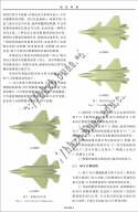
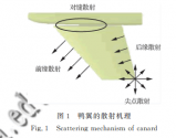

I don't know if anyone posted it already, though I like to share this regarding the pro and cons of the canard design on RCS.
There is a research paper addressing the issue in a Chinese publication titled "Radar cross-section effect of canard"
You can download the pdf file at
Basically what they did is use the more accurate MLFMM (multi level fast multipole method) to simulate instead of the Physical Optics simulation algorithm used in "A Preliminary Assessment of Specular Radar Cross Section Performance in the Chengdu J-20 Prototype" by Dr. Carlo Kopp.
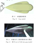
After that, they built a canard model to run the RCS test in the anechoic chamber.
View attachment 96936
View attachment 96937
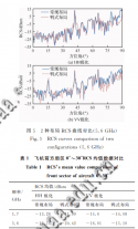
Key takeaway in the paper for canard vs. conventional configuration.
1. Neglectable frontal RCS increase compare to conventional under cruising conditions within +-5° deflection.
2. Side RCS is lower than conventional due to no secondary reflection between vertical stabilizer and horizontal stabilizer.
View attachment 96938
Ways to mitigate
1. Apply RAM to the gap between the fuselage and canard
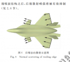
2. Chamfer the rear edge of the canard to reduce scatter
3. Trailing edge parallel to the main wing on the other side
4. Use appropriate structure and RAM material on the trailing edge
View attachment 96940
View attachment 96939
I think this picture shows exactly what those mitigate methods on the J-20
View attachment 96942
Another example of "everything must be parallel" on stealth fighters is the sawtooth pattern. One side of the sawtooth pattern is parallel to the corner clip on the trailing edge of the canard, while the other side of the pattern is parallel to the leading edge of the canard.I think this picture shows exactly what those mitigate methods on the J-20
View attachment 96942
Then, why don't crop the tip in the front of the canard?Cropping the canard tip and adding sawtooth patterns also helped, with the former reducing RCS by several magnitudes when the canards are deflected between 5 to 15 degrees.
Then, why don't crop the tip in the front of the canard?
The trailing tip is cropped, not the one at the front. I think that's what he means.I am not quite sure I follow.
The trailing tip is cropped, not the one at the front. I think that's what he means.
