055 DDG Large Destroyer Thread

Status
Not open for further replies.

Solaris

Banned Idiot
since 052c\d have x band radar on top of their mast for what some say is early warning low altitude purposes and surface search, i do imagine 055 might feature a similar radar.

That radar on top of the 052C/D's mast is not an "early warning" radar. It is a surface search radar for the purpose of cueing the 730 CIWS and HQ10 launchers; in this capacity a similar kind of radar may end up on the 055. The actual early warning radar on the 052C/D is the Yagi antenna on the back of the ship.
 

Engineer

Major
Sure! but they could also do it so they can forgo a quarter of the side of the deckhouse to avoid having to install a side array.


My main point is that at this moment, it is very premature to consider the idea they will do something like only installing one side of the deckhouse with arrays. They might end up doing that, who knows, but there is nothing from either past PLAN practise or physical indication of the mock up at present to suggest it.

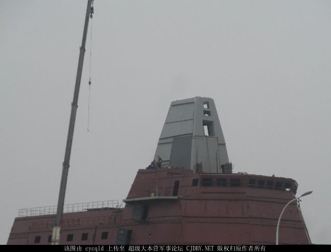
Yet, it looks like installing just one side of the deck house with arrays is what they are doing. Take a close look at the picture posted by no_name:
102632kikeeik5wlmwdsse_zps4f9cf5a2.jpg


While it is difficult to spot, you can see an opening just underneath the streetlamp. So, there is indeed an opening for the S-band array on the port side, even though there is no opening on the starboard side.
 

Blitzo

Lieutenant General
Staff member
Super Moderator
Registered Member
Yet, it looks like installing just one side of the deck house with arrays is what they are doing. Take a close look at the picture posted by no_name:
102632kikeeik5wlmwdsse_zps4f9cf5a2.jpg


While it is difficult to spot, you can see an opening just underneath the streetlamp. So, there is indeed an opening for the S-band array on the port side, even though there is no opening on the starboard side.


I'm not sure if that is an opening, the angle of the picture and the prevalence of many metallic lines on the mock up make such a judgement from current photo angles, dubious at best.

If it turns out that there is indeed a hole there for an array and that only the port side holes were cut when the photo was taken, then great. But that is not necessarily indicative of what the final configuration will be like given the picture might have been taken when they had only cut out the port side holes before cutting out the starboard ones.
There are any number of more likely reasons for why the port side holes might have been cut out first before the starboard ones, before arriving to the idea that they are choosing to only install arrays on the port side.


Now, I'm definitely not ruling that possibility out, and you can consider my stance redacted if it turns out that is the case once we get more photos in a few days or weeks showing only the port side equipped with arrays. But at this point I think it would be a leap of faith to say they plan to only install arrays on the port side, due to limited photographic evidence.
 

no_name

Colonel
Some nice pictures of what the final mast and deckhouse may look like. Probably worth noting that the final mast may feature a fair few more holes than the three sets we see now, especially if the mast is only half completed and is planned to go higher.

4xTNzGx.jpg


94f5Cyq.jpg

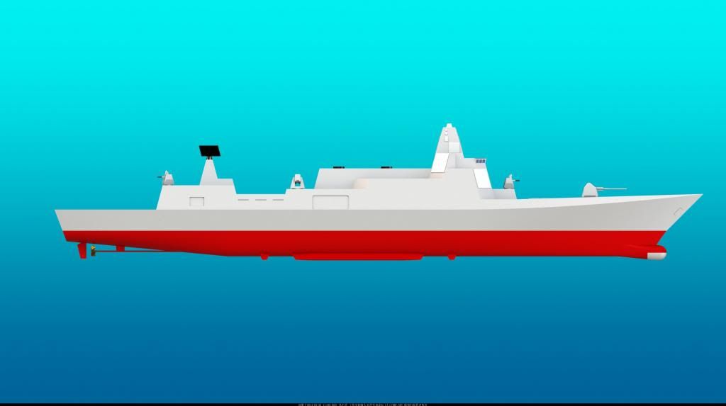
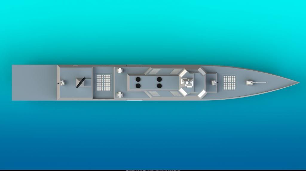
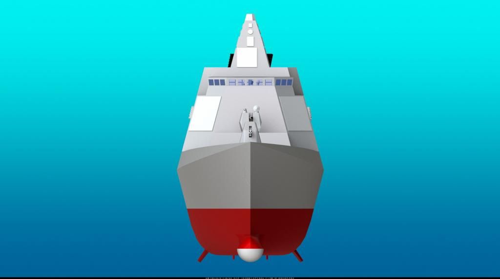
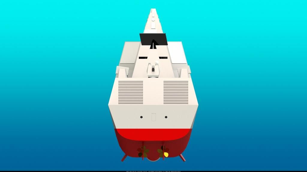
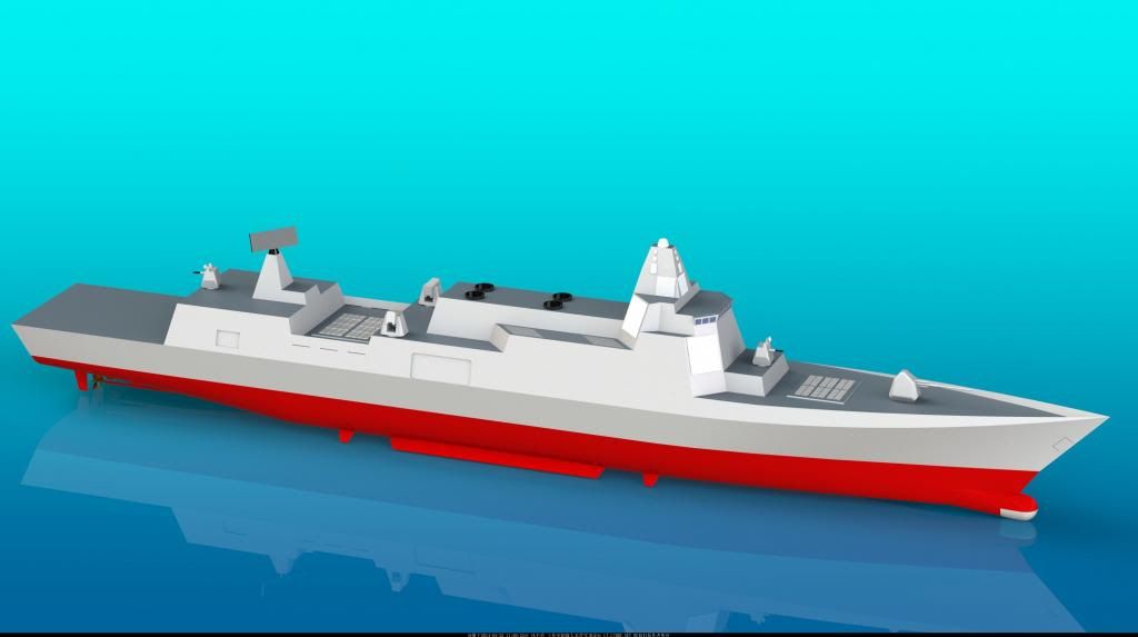
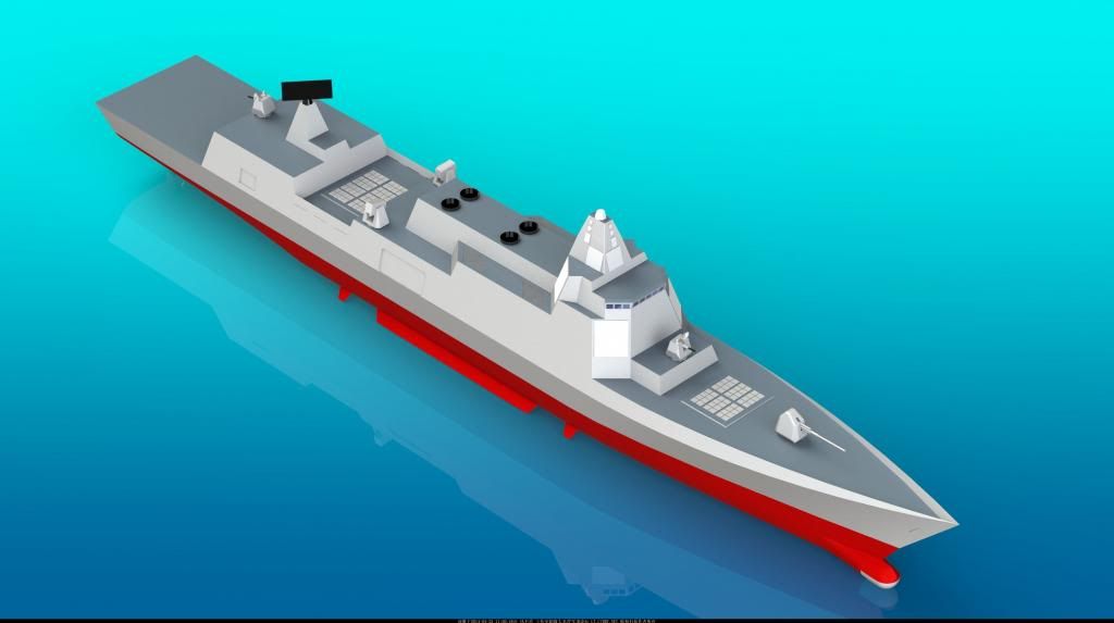
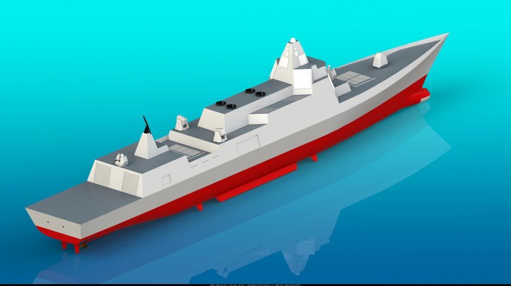
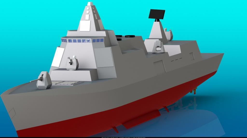
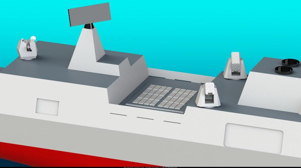
Some guy's rendition of what I think is the same design:

1-2.jpg

2-2.jpg

3-2.jpg

4-2.jpg

5-1.jpg

6-1.jpg

7-1.jpg

8-1.jpg

9-1.jpg
 

Blitzo

Lieutenant General
Staff member
Super Moderator
Registered Member
Strange that they didn't have 8 VLS modules up front as well, but the overall configuration of the ship is in my mind probably more likely what the real thing will look like
 

Engineer

Major
I'm not sure if that is an opening, the angle of the picture and the prevalence of many metallic lines on the mock up make such a judgement from current photo angles, dubious at best.

If it turns out that there is indeed a hole there for an array and that only the port side holes were cut when the photo was taken, then great. But that is not necessarily indicative of what the final configuration will be like given the picture might have been taken when they had only cut out the port side holes before cutting out the starboard ones.
There are any number of more likely reasons for why the port side holes might have been cut out first before the starboard ones, before arriving to the idea that they are choosing to only install arrays on the port side.


Now, I'm definitely not ruling that possibility out, and you can consider my stance redacted if it turns out that is the case once we get more photos in a few days or weeks showing only the port side equipped with arrays. But at this point I think it would be a leap of faith to say they plan to only install arrays on the port side, due to limited photographic evidence.

PLAN is obviously not choosing to install arrays just on the port side of the actual ship. What others have suggested is that the arrays are only installed on the port side for the land based facility, because there isn't anything to block the view on that side.
 

Blitzo

Lieutenant General
Staff member
Super Moderator
Registered Member
PLAN is obviously not choosing to install arrays just on the port side of the actual ship. What others have suggested is that the arrays are only installed on the port side for the land based facility, because there isn't anything to block the view on that side.

C'mon, I never said they were planning on only installing arrays on the port side.on the actual ship, I was talking about the mock up as well.

What do you mean by block the view? From what I've read everyone of the opinion that only the port side of the mock up will have arrays arrives there because of the photo showing a lack of holes on starboard along with holes on the mast for forward and port mast arrays and possible port opening for the S band radar. But that can be explained away by the possibility that they simply hadn't cut open the starboard holes when the photo was taken.

Maybe I missed a reply, but I've seen no one mention anything on the starboard side of the mock up blocking the arrays field of view (if that is what you meant).
 

Solaris

Banned Idiot
Some guy's rendition of what I think is the same design:

2-2.jpg

5-1.jpg

7-1.jpg
The one thing these fanart drawings do is they always incorrectly represent the relationship of the stacks and the air intakes. I'm no expert in marine propulsion, but I've noticed that COGAG ships usually have the business ends (power shafts) of each pair of GT's facing each other. I presume this is to have both of them inputting torque into the same gearbox in the most efficient manner possible. Externally this means that the air intake systems would be located forward of the forwardmost stacks and rearward of the rearmost stacks. The Arleigh Burke design is a perfect example of what I'm talking about.

For this particular set of fanart 055 drawings, if the air intakes are placed correctly, it will put the aft GT's being at risk of sucking in HQ-10 or VLS exhaust every time one of these things fires a missile. Also, horizontal air intakes on a ship are probably not a good idea in general.
 

Blitzo

Lieutenant General
Staff member
Super Moderator
Registered Member
The one thing these fanart drawings do is they always incorrectly represent the relationship of the stacks and the air intakes. I'm no expert in marine propulsion, but I've noticed that COGAG ships usually have the business ends (power shafts) of each pair of GT's facing each other. I presume this is to have both of them inputting torque into the same gearbox in the most efficient manner possible. Externally this means that the air intake systems would be located forward of the forwardmost stacks and rearward of the rearmost stacks. The Arleigh Burke design is a perfect example of what I'm talking about.

I'm not very knowledgeable such matters either, but what of the ticonderogas? Their air intakes seem to be right alongside its smoke stacks, not particularly forward or rear. But then again maybe I'm looking at the ship wrong.

For this particular set of fanart 055 drawings, if the air intakes are placed correctly, it will put the aft GT's being at risk of sucking in HQ-10 or VLS exhaust every time one of these things fires a missile. Also, horizontal air intakes on a ship are probably not a good idea in general.

I wouldn't say the air intakes are particularly in danger of taking in VLS exhaust, at least compared to other ships in terms of the location of the intakes on the vessel relative to the VLS. The ship would constantly steam forwards I imagine, during combat, so the rest of the hull aft of the forward VLS will move "under" the exhaust of fired missiles. burkes, ticos, and virtually any other normally designed surface combatant has air intakes positioned amidships around the centreline that will cross under any forward VLS exhaust. And I don't think the side facing air intakes of those ships versus upward facing intake of the CGI 055s will show major differences in amount of potential exhaust sucked in.

I don't think HQ-10 makes that much exhaust when firing either, and from its positioning, it is very much aft of the air intakes so I doubt they will suck in what little smoke is there. But then again I've never stood next to an air intake on a DDG during operation so maybe I'm wrong.


I'm also not sure if the air intakes opening face is on a poor axis. I imagine there must be other ships where they face upwards rather than sideways. Would the only danger be rainwater?
 
Last edited:
Status
Not open for further replies.
Top