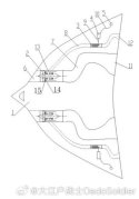
Thank you for posting that. So according to the patent, there is a compressor stage (number 14 on the drawing) that is connected to the compressor shaft via a clutch (number 15 on the drawing) and while the clutch is disengaged, it works as a variable guide vane. When an energy weapon is set to be activated, the controller determines how much power the specific weapon requires, engages the clutch and fires up number 14 and actuates its blade pitch in order to supercharge bypass the airflow and maintain bypass ratio, opens up the throttle body of the turbine duct to a specified position based on how much power is required by the energy weapon, then adjusts the combustor fuel injection and actuates other guide vane angles based on the changes in the turbofan state caused by the previous steps as well as the speed of the aircraft. The patent also states that should the turbine need an S-shape exhaust (I guess for LO applications), it can be done without problems. The patent also states that the exhaust of the turbine (number 12 on the drawing) can be designed to provide a bit of thrust and reduce waste.Here's the . The system is designed to power multiple direct energy weapons without affecting the operation of the main turbofans.
It is a nice design. I guess what they mean by it not affecting the operation of the turbofan, is that the turbine doesn't have any direct mechanical links to the turbofan, and this system is designed to turn on and off frequently on demand, which means if it were to be an IDG with a clutch, it would shock the engine every time it is activated, as opposed to this design, which produces significantly less shock.

Last edited:


