Naval missile guidance thread - SAM systems

Tetrach

Junior Member
Registered Member
Curiously, the MBR equipped Flight III Burke appears to retain the mechanical illuminators.

Source:
Please, Log in or Register to view URLs content!

What do you mean by MBR ? what is its signification

also, you never concluded if SPQ-9 was for mid course correction I think. what's the consensus ?
 
Last edited:

Tam

Brigadier
Registered Member
Hmm. The 68 sub arrays were for the receivers, which outnumber the radiators. The radiators have only 32 sub arrays. The original arrangement was 2R arrays for 1T array. The Wikipedia article appears to be describing the original configuration of the radar. In the section on SPY-1B, they state the following:

No mention of the subarray configuration here.


Your numbers are not right. Flight IIA ships come with 3 generators of 3MW. Flight III ships will have 3 generators of 4MW each.

If you fire all the 32 CFAs through a single face, as any sane designer would, the power consumption will not exceed what the ship can provide. The radar is operated in pulse mode, not in CW. Because of that, there is ample time to fire through the other 3 faces while the first face is listening to echoes.

Yes, you rotate through the faces. Actually I think the radar uses one face much longer than a single pulse cycle, with each face sweeping its entire quadrant first before moving to the next one, or it can stay with one face or two faces if the threats are in that quadrant and the radar is engaged with the targets.

Later model allows for operation of two faces simultaneously, and this possibly means in any order of the four. The later model has a transmitter output of 6mw, so 3mw per active face if two face mode, or 6mw with one face mode.

I don't understand why you would want to design your radar so that it can use only a 1/4 of the available power.

Well, you said the radar is AESA-PESA hybrid. If 32 CFA is dedicated for a single face alone, that means each face alone is already 4.2 to 6mw, and four faces is already 16.8 mw if operating simultaneously. This exceeds the 7.5mw power available on Flight I and II Burke and the 9mw power available on Flight IIa. Its also greater than the 12mw power available on the Flight III. The alternative would be 8 CFA per face, with the total output of all faces up to 4.2mw or 6mw on later ships, which means about over 1mw per face maximum, but all four faces can be used simultaneously. So the radar cannot be a hybrid in terms of transmission model but a true PESA, the transmitter is a cluster of 32 CFA, and is multiplexed between the four faces. SPY-1 is also unique for a PESA for having a multiplexing transmitter, as a PESA usually means one transmitter per face.

Note this should be different on the Tico, whose arrays are divided into two deckhouses. This means it has two transmitters, each with 32 CFA.

Now I am intrigued. I will try to get my hands on a copy of this book.
 

nlalyst

Junior Member
Registered Member
Well, you said the radar is AESA-PESA hybrid.
I got triggered to say that after reading on the Wikipedia article that there are 8 transmitters:
Transmitting arrays are driven by eight transmitters, each with four
Please, Log in or Register to view URLs content!
(CFAs)

If 32 CFA is dedicated for a single face alone, that means each face alone is already 4.2 to 6mw, and four faces is already 16.8 mw if operating simultaneously. This exceeds the 7.5mw power available on Flight I and II Burke and the 9mw power available on Flight IIa. Its also greater than the 12mw power available on the Flight III.
These power values are for the pulses. You don't need that much power on the input side.
 

Anlsvrthng

Captain
Registered Member
Here are example.


Yes, beamforming which is also known as spatial filtering, along with pulse compression and Doppler filtering.

Note how those diagrams match with this physical example which happens to be a module for Phazotron's Zhuk AESA radar.


Note that T/R does not necessarily mean TRM. TRM means T/R per module. DTRM is Dual T/R per Module or two T/R in one module. QTRM is Quad T/R per Module. The above example is a QTRM, and is actually more common with high frequency band like X band. You may not need to put a FPGA behind every T/R, but one in four is good.

It doesn't tell what could be done with a DSP on each element.

There is a master clock on every phased array radar, phase shifters , and radiating elements.

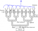
Now, the difference between AESA/PESA is in the case of PESA the signal amplification happens before the phase shifter, in the chase of AESA it happens after the phase shifter.

It means the AESA has a good 3db advantage on the transmitter and 3db on the receiver side.

The current generation USA radars use GaAs , and that has good 4-10 w/element performance .

The Irbis-e can generate 20 kW, it is around the capability of the GaAs.

But the AESA has 6db advantage on the Tx/Rx.

But the IRbis use receiving elements on each antenna, means the disadvantage is only 3db

To make the situation even more complicated, the Irbis can be rotated, that negate all transmitting advantage of the AESA, considering the rotation can give max 3db signal increase.


Now, having computer on each element how can help ?
The element receiving signal from an omnidirectional dipole, means there is nothing really to process/analyse.
Only the central receiver behind the phase shifters "see" the spatial picture.


All that the DSP in the element can do is to do same AD transformation, maybe controlling the phase shifter behind the backplane, and there is nothing else really.

OF course it can be used to make sub arrays and different channels, but that dramatically decrease the radar performance, and the PESA can do that as well with multiple emitters or multiple pulse .

No one can forget that cutting to half the radiation surface to scan with two beam actually will decrease the search volume by 80%.

So, fifth of the volume can be searched twice fast. wow.

The multi beam and all other thing is as interesting from warfare standpoint like the discovery of a 9 leg spider.
 
Last edited:

Tam

Brigadier
Registered Member
I got triggered to say that after reading on the Wikipedia article that there are 8 transmitters:


These power values are for the pulses. You don't need that much power on the input side.

No. These are power fed by the generators to the arrays. Power transmitted at the face of the array is much less due to losses.
 

Tam

Brigadier
Registered Member
It doesn't tell what could be done with a DSP on each element.

There is a master clock on every phased array radar, phase shifters , and radiating elements.

Now, the difference between AESA/PESA is in the case of PESA the signal amplification happens before the phase shifter, in the chase of AESA it happens after the phase shifter.

No. In both cases, it happens before the phase shifter, but with the AESA, it happens just below the phase shifter, while on the PESA it happens way way back behind the phase shifter, like way way way way back behind the array itself. There is a central amplifiier and signal generator and then you have parallel lines from this unit to each element. Signal transfer from the central amp/waveform generator to each emitter element on the array has insertion losses which AESA only experiences minmally.


It means the AESA has a good 3db advantage on the transmitter and 3db on the receiver side.

The current generation USA radars use GaAs , and that has good 4-10 w/element performance .

The Irbis-e can generate 20 kW, it is around the capability of the GaAs.

But the AESA has 6db advantage on the Tx/Rx.

But the IRbis use receiving elements on each antenna, means the disadvantage is only 3db

Many PESA, in fact I tnink most PESA have seperate receiver elements. IRBIS is nothing different from them.

To make the situation even more complicated, the Irbis can be rotated, that negate all transmitting advantage of the AESA, considering the rotation can give max 3db signal increase.

Nope. In the case of fighter AESA, these can also be rotated.

Now, having computer on each element how can help ?
The element receiving signal from an omnidirectional dipole, means there is nothing really to process/analyse.
Only the central receiver behind the phase shifters "see" the spatial picture.

I already said filtering. For example the computing on the receiving end removes unwanted signals or clutter, so only the relevant signals are sent down to the radar's main computing unit. On the output end, the transmit element would adjust itself based around the output of the neighboring elements.

Another example, just read the introduction.
Please, Log in or Register to view URLs content!

All that the DSP in the element can do is to do same AD transformation, maybe controlling the phase shifter behind the backplane, and there is nothing else really.

Phase shifter control is through the SoC implemented through the FPGA, and these are all connected by a bus throughout the entire array.

OF course it can be used to make sub arrays and different channels, but that dramatically decrease the radar performance, and the PESA can do that as well with multiple emitters or multiple pulse .

No. Not with a single central amplifier and signal generator. In a PESA, all the waveforms are generated by a single source, and nothing else modifies it along the way to the emitter. So all the emitters emit the same waveform. With AESA, every single module has their own amplifier and signal generator, and you can vary the frequencies and the timing across the face.

No one can forget that cutting to half the radiation surface to scan with two beam actually will decrease the search volume by 80%.

So, fifth of the volume can be searched twice fast. wow.

The multi beam and all other thing is as interesting from warfare standpoint like the discovery of a 9 leg spider.

Far more important than multibeam is frequency agility. Each AESA module uses a solid state digital amp and signal generator, while a PESA has to use an analog unit, like klystron, amplitron, TWT and so on which are all essentially cathode ray tubes. The result of this is that AESA can change its waveforms much more rapidly and drastically. This allows the AESA to rapidly change its waveforms in response to an ECM response, constantly varying frequency and phase. PESA has implemented its own frequency agility measures but its nowhere like an AESA can do with its digital solid state signal generators. For this reason, AESA or solid state radars are better for implementing LPI, or Low Probability of Intercept. This means the signals being emitted by such radars would have a much more difficult time of being identified by an enemy receiver or ESM. These signals would look like static or background noise, and enemy ESM would be fooled into disregarding them as such, and thus would not cause any alarm or notification.

LPI integrates well with stealth craft, planes or ships, because you essentially have 'stealthy' radar.
 

nlalyst

Junior Member
Registered Member
No. These are power fed by the generators to the arrays. Power transmitted at the face of the array is much less due to losses.
A source in the article you posted claimed the pulses are in the low MW range for an unspecified pulse duration. I understood that's out of the array. Assuming a pulse length of 1us and a power of 4MW, that's just 4J being radiated out.
 

nlalyst

Junior Member
Registered Member
With AESA, every single module has their own amplifier and signal generator, and you can vary the frequencies and the timing across the face.
Not quite. Every module has its own HPA, but the signal generator is typically centralized, either for a subarray or an entire array. In this regard it may not be any different than a PESA. I am not saying your example is wrong, rather that there are AESAs that are built differently.

No. In both cases, it happens before the phase shifter, but with the AESA, it happens just below the phase shifter.
Not in the diagrams that I saw. The HPA was clearly after the phaseshifters in an AESA. There was a preamp before the phaseshifters.
 

nlalyst

Junior Member
Registered Member
PESA has implemented its own frequency agility measures but its nowhere like an AESA can do with its digital solid state signal generators.
PESAs may also use solid state signal generators, so no difference there.
 

Tam

Brigadier
Registered Member
Not quite. Every module has its own HPA, but the signal generator is typically centralized, either for a subarray or an entire array. In this regard it may not be any different than a PESA. I am not saying your example is wrong, rather that there are AESAs that are built differently.


Waveform generator on an AESA is placed after the digital beamformer and prior to the analog beamformer.

AESA-Radar-Block-Diagram.jpg


Not in the diagrams that I saw. The HPA was clearly after the phaseshifters in an AESA. There was a preamp before the phaseshifters.

Would be neat to see those diagrams.

After the phase shifters, you only have the antenna. I don't see how you can put an amp or anything but the antenna beyond the phase shifters.


main-qimg-72196885a47ef6dc1aa7a2abe233880c.png
 
Last edited:
Top