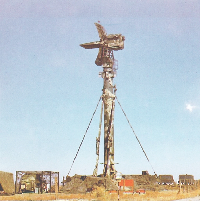
Naval missile guidance thread - SAM systems

Anlsvrthng

Captain
Registered Member
I will have to digest this a bit. I was originally thinking that the data rate would be derived from the radar bandwidth, which I expected to be in the range of 400MHz and the sampling rate would not need to be higher than 800MHz in that case ...

After googling a bit, I ran into this guy:
Please, Log in or Register to view URLs content!


It's a RF sampling receiver (ADC) from TI supporting 9GHz input bandwidth, but with only 6.4 giga samples/s max sampling rate. That should lead to some aliasing in the output? Also, the resolution is less than in your example: 12 bit.

It dumping 6GByte/sec to a card, but exactly what the other card can do with it ?

And it is still small to do spatial separation of signals.
I will have to digest this a bit. I was originally thinking that the data rate would be derived from the radar bandwidth, which I expected to be in the range of 400MHz and the sampling rate would not need to be higher than 800MHz in that case ...

After googling a bit, I ran into this guy:
Please, Log in or Register to view URLs content!


It's a RF sampling receiver (ADC) from TI supporting 9GHz input bandwidth, but with only 6.4 giga samples/s max sampling rate. That should lead to some aliasing in the output? Also, the resolution is less than in your example: 12 bit.
400 MHz coming from the resonant frequency of the dipoles.

It worth to check the fan on the data capture card - and it is NOT the DSP that required to process anything with this data.

There are oscilloscopes out there with these capabilities.
 

Anlsvrthng

Captain
Registered Member
I will have to digest this a bit. I was originally thinking that the data rate would be derived from the radar bandwidth, which I expected to be in the range of 400MHz and the sampling rate would not need to be higher than 800MHz in that case ...

After googling a bit, I ran into this guy:
Please, Log in or Register to view URLs content!


It's a RF sampling receiver (ADC) from TI supporting 9GHz input bandwidth, but with only 6.4 giga samples/s max sampling rate. That should lead to some aliasing in the output? Also, the resolution is less than in your example: 12 bit.
Please, Log in or Register to view URLs content!

Article from 2003 , 2 GHz sampling rate with 8 bit, at X band.
400 MHz bandwidth sampled with this speed.
 

nlalyst

Junior Member
Registered Member
Please, Log in or Register to view URLs content!

Article from 2003 , 2 GHz sampling rate with 8 bit, at X band.
400 MHz bandwidth sampled with this speed.
Hmm, I cannot open the page in the book you linked.

Reading back a few pages in this thread, there was a discussion about missile command guidance and you pointed out how the Irbis radar can receive echoes at the same time it is transmitting. This is because it seperates receive antennas from transmit antennas, on a 1:1 basis?
 

Anlsvrthng

Captain
Registered Member
Hmm, I cannot open the page in the book you linked.

Reading back a few pages in this thread, there was a discussion about missile command guidance and you pointed out how the Irbis radar can receive echoes at the same time it is transmitting. This is because it seperates receive antennas from transmit antennas, on a 1:1 basis?
I haven't said that, I said that it can give multiple spatial direction during the echo .

As I spent same time to think about it I realised it can't be like that, this kind of AESA would require massive oversampling of the carrier (X band) signal, and there is no processor fast enough for that.
So I was wrong, but sadly no one spot it : (

To receive and transmit at the same time a radar needs separator blade like this :

LEMZ-76N6-Clam-Shell-1S.jpg
 

Anlsvrthng

Captain
Registered Member
However, as I thinking about it actually what is the benefit to have a AD+DSP in each element ?

They can't do transformation, all that can happens at the element is AD transformation and band-pass filtering.

What else can be done with a DSP at the element ?
 

Tam

Brigadier
Registered Member
Hmm, I cannot open the page in the book you linked.

Reading back a few pages in this thread, there was a discussion about missile command guidance and you pointed out how the Irbis radar can receive echoes at the same time it is transmitting. This is because it seperates receive antennas from transmit antennas, on a 1:1 basis?

All fighter radars do this, since the time the first radars get SARH missile guidance illumination, like in for the AIM-7 Sparrow. That goes back to the Vietnam War Days. CWI allows both transmit and receive on the same antenna, even using parabolic, cassegrain, inverse cassegrain, conical scan antennas. Because of interference going both ways, not the best for range however.
,
 

nlalyst

Junior Member
Registered Member
However, as I thinking about it actually what is the benefit to have a AD+DSP in each element ?

They can't do transformation, all that can happens at the element is AD transformation and band-pass filtering.

What else can be done with a DSP at the element ?
The Altera paper I linked, had this to say:
"Modern radars have an analog interface to the antenna or antenna elements, but the
analog signals are converted to digital signals for processing. The receiver typically includes downconversion and beamforming elements. The emitter includes pulse generation, beamforming, and digital up conversion."
 

nlalyst

Junior Member
Registered Member
All fighter radars do this, since the time the first radars get SARH missile guidance illumination, like in for the AIM-7 Sparrow. That goes back to the Vietnam War Days. CWI allows both transmit and receive on the same antenna, even using parabolic, cassegrain, inverse cassegrain, conical scan antennas. Because of interference going both ways, not the best for range however.
Hmm. What about FCMW radars? The examples I found clearly show two antennas: one for Tx, and one for Rx, like this one:
Please, Log in or Register to view URLs content!
 

Tam

Brigadier
Registered Member
All fighter radars do this, since the time the first radars get SARH missile guidance illumination, like in for the AIM-7 Sparrow. That goes back to the Vietnam War Days. CWI allows both transmit and receive on the same antenna, even using parabolic, cassegrain, inverse cassegrain, conical scan antennas. Because of interference going both ways, not the best for range however.
,

To clarify, back in the older days, transmit and receive with CWI and communication, which runs on CWI, are done on a single antenna since Day One. Having seperate receive and transmit antenna is an evolution to improve from this model.

Reading back a few pages in this thread, there was a discussion about missile command guidance and you pointed out how the Irbis radar can receive echoes at the same time it is transmitting. This is because it seperates receive antennas from transmit antennas, on a 1:1 basis?

IRBIS is PESA, correct? PESA also have separate receive and transmit elements; difference between AESA and PESA is on the transmission side. But once again, if a radar is sending and transmitting at the same time, without any duty cycle, the radar is in CWI mode, tracking a target while illuminating it for a semi active radar homing missile during its terminal stage.

If the missile is in the inertial and midphase mode, the radar can still be in pulse, with duty cycles, tracking a target, with the guidance information uploaded to the missile via datalink. Then on the terminal stage of the missile, the fighter radar goes into CWI mode, illuminates the target for the SARH type missile. For the pilot, this is STT or Single Target Tracking. You only need to do this with SARH missiles like R-72. No need to do this on an active radar homing missile like R-77 where the missile is "forget" at the terminal stage.
 

Tam

Brigadier
Registered Member
Hmm. What about FCMW radars? The examples I found clearly show two antennas: one for Tx, and one for Rx, like this one:
Please, Log in or Register to view URLs content!

Modern examples.

FMCW is a variation of CW, and can do recieve and transmit at the same time, either with separate recieve or transmit elements, or through a single antenna like in old examples.

McDonnell-Douglas-F4-Phantom-Radar.jpg images (12).jpeg


Even with separate Rx and Tx elements, there is still interference because you got both waves coming bidirectionally. That is why pulse radar was invented, to have separate Recieve and Transmit.

FMCW was invented so you can get range with CW by putting a marker on the wave. With pure CW, you cannot get range as pure sinusoidal waves without any variation can't have a marker that you can use to tell for range, you only get heading and speed measurements. Ground based fire control radars that illuminate for SAMs while tracking targets at the same time, run on FMCW. You take a radar like this, for the S-300, which tracks target and lights them for the missile, runs on FMCW. The panel receives and transmits at the same time. Equal number of Rx and Tx elements are not necessary. Sometimes Rx elements are more.

30N6E_5N63S_Flap_Lid_B_tracking_and_missile_guidance_radar_S-300PMU1_SA-10_Grumble_Russia_Russ...jpg
 
Top