Ah, this is a bit different from the idea with the J-20’s inlet mesh, since it’s about cleaning up any residual boundary layer that the bump doesn’t deflect, as opposed to expelling or ingesting extra air to adjust pressure inside the inlet tunnels. Similar working principles but applied to different control theories I think.Unfortunately, I did not save it when I first read it years ago. I think it may be this one, but it is not available for download or viewing anymore.
If my memory serves me right, the paper that I read did not say "JF-17", but the diagram of the bump in it was certainly of JF-17.
You are using an out of date browser. It may not display this or other websites correctly.
You should upgrade or use an alternative browser.
You should upgrade or use an alternative browser.
J-20 5th Generation Fighter VII
- Thread starter siegecrossbow
- Start date
- Status
- Not open for further replies.
I think what you are saying is from the abstract of the paper (which is the only part viewable). Yes the abstract was talking about the bleeding holes on the bump, it did not say anything about the bleed on the intake tip. But maybe it is in the content, I am not very sure.Ah, this is a bit different from the idea with the J-20’s inlet mesh, since it’s about cleaning up any residual boundary layer that the bump doesn’t deflect, as opposed to expelling or ingesting extra air to adjust pressure inside the inlet tunnels. Similar working principles but applied to different control theories I think.
Also note that the author has multiple studies on DSI, so the intake bleeding holes may be covered in another paper of his that I read.
Abstract
The present work is an extension of our earlier computational study [24] on an integrated Diverterless Supersonic Inlet (DSI) where complete external and internal (intake duct) flow features along with intake performance characteristics were presented. In this paper the computed flow and performance characteristics at low angle-of-attack (AOA) of a passive bleed system on the same DSI are presented near intake design mass flow rate. The passive bleed system comprises of a porous wall segment on the bump compression surface that is connected to a bleed chamber with a single outlet exposed to a specific pressure. The bleed mass flow rate is controlled through controlling the bleed chamber outlet pressure. The subsonic characteristics of this passive bleed system on the DSI are evaluated at M∞=0.8 while the supersonic characteristics are evaluated at M∞=1.7, which is near the design Mach number for the intake. The results of the present study indicates that although some low energy bleed chamber air seeps into the intake duct at M∞=0.8, however the passive bleed system on the whole results in some improvement in engine face total pressure recovery due to removal of part of bump compression surface residual boundary layer. At supersonic conditions (M∞=1.7) the boundary layer diversion mechanism behind the shock wave [24] prevents the low energy bleed chamber seepage air, along with upstream boundary layer from entering the intake duct. However, the passive bleed system results in significant deterioration of engine face total pressure recovery due to its affect on the inlet shock wave structure and related flow field.i wish this pic is in wallpaper res... no water mark of course...
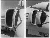
Same principal at work here on the ancient Grumman F11-F1F Super Tiger:Unfortunately, I did not save it when I first read it years ago. I think it may be this one, but it is not available for download or viewing anymore.
If my memory serves me right, the paper that I read did not say "JF-17", but the diagram of the bump in it was certainly of JF-17.

Lethe
Captain
i wish this pic is in wallpaper res... no water mark of course...
Ask and ye shall receive.

Thank you!Ask and ye shall receive.

by78
General
A newly released old image.

The same perspective, but with domestic engines.

- Status
- Not open for further replies.


