Exactly the same point I was making before in reference to AWACS using UHF band radars to detect J-20s which are NOT optimized to defeat such bands. I feel on the one hand the same people would gladly extol the stealth-defeating features of these Chinese anti-stealth radars while at the same time refusing to believe (or at least acknowledge) that the J-20 is vulnerable to detection by the exact same mechanisms. It's amazing, frankly.All stealth airplane designed for X band low detect-ability.
X band has a wavelength of centimetre, and it is usable only for active or semi active missile homing.
To have low detectability in this band they need to decrease as low as possible the number of edges on the airplane, and cover them with RAM in comparable thickness \to the wavelength. All other surface will be dominated by geometric scattering.
So, the S band has a wavelength of 10 cm, and the VHF is meter , means the RAM is useless, the airplane can be considered as a big edge, with smaller (S band) or no (VHF) geometric scattering .
Means the effective radar cross section of an f-22 , even if the x band is as big as a square cm (require extremely costly maintenance procedures) in VHF will be several square meter.
Of course it just solve the detect-ability issue, the SAM missiles still not usable.
You are using an out of date browser. It may not display this or other websites correctly.
You should upgrade or use an alternative browser.
You should upgrade or use an alternative browser.
Chinese Radar Developments - KLJ series and others
- Thread starter indochina
- Start date
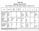
Like a MIG25 or F-111.Are any sources available for stealth fighter RCS in L or UHF bands or detection distances using AWACS?
There is no difference between them on that frequency.
Okay, but sources?Like a MIG25 or F-111.
There is no difference between them on that frequency.
Okay, but sources?
I was thinking of something more specific. I don't imagine we'll be doing any calculations from first principles here.
Don't need to.I was thinking of something more specific. I don't imagine we'll be doing any calculations from first principles here.
The way that the VHF/UHF radar detect the aircraft is equivalent to the optical particle counting methods.
It doesn't depend on the details of the aircraft, it affected by the ratio between the radar wavelength and the aircraft size.
The scattering works by the same way with the light.
Means that if the particle is way bigger than the light then the reflection depending on the shape.
If the particle is as big as the light wavelength, or close to it then it will have weak connection with the shape, the defining parameter will be the size (and even the small effect of shape will just shift the peak frequency , not attenuating it to the monostatic radar like the shaping of the f35 )
I've since come across this comment on Key Publishing Aviation Forums. It's not definitive, but it's better than anything else I've seen.Are any sources available for stealth fighter RCS in L or UHF bands or detection distances using AWACS?
:
[...]
Another food for thought i would like to present is the Radar Cross Section variable. This topic is admittedly very complex yet unavoidable if one wish to actually make better guesswork on radar performance. The big question is "What RCS value i have to fill for the variable ?". Given the multiple dependence nature of RCS. 0.001 sqm in one frequency would not be valid in another and one may not always have access to more complex modeling or information. Especially if one wish to do the assessment for low observable target.
As we know that there is wavelength dependency of RCS, i concentrated my efforts towards it. The "Radar Cross Section 2nd Edition" book by Knott and Tuley had the squared wavelength dependency, which need to be understood as base. It turns out that the dependency is basically a base 20 Logarithm of the frequency in question subtracted by the "target frequency". Example of use.
We have an object designed to have 0.001 sqm or -30 dB RCS in 3 cm wavelength, what's the likely RCS in L-band of 24 cm ?
We first do some logarithm works :
The 3 cm band (0.03 m)
20*LOG(0.03) = -30
Then the 24 cm band (0.24 m)
20* LOG(0.24) = -12
The we subtract the first band with second one. Thus. -30-(-12)=-18 Now we see the 18 dB difference. We can further subtract the RCS of the object in dB with the resulted value from our first equation.
RCS in L-band= -30-(-18)
RCS in L-band = -12 dB or 0.06 Sqm.
There are however always an exception as one cannot generally use the squared wavelength dependence on all stealth objects. As described in following papers :
and for those who interested in promises and features of low frequency radars the 2nd part of the paper
The squared wavelength dependence appears to only applies toward conical object or ogival, which would make it suitable for predicting missile weapon RCS. Other military systems which does not exhibit such shape might follow wavelength dependence (which if one interested can be run down with same procedure i described BUT using 10 as multiplier instead of 20).
and now the question is "Which dependence i should use to fill ?" This is mostly based on my own simple observation. Based on what was available, especially with this famous image, courtesy of secretprojects.
The object with many facets (the lockheed Have Blue) appears to follow the squared wavelength dependence while the Northrop XST which incorporates some curvi-linear elements (This feature would be observed in subsequent stealth fighters and missiles like YF-23A and B-2). One can see the dependence from the difference of RCS between high band (the X-K band) with the one in the lower 175 MHz band. The faceted have blue have 30 dB more RCS which quite close to the squared wavelength approximation (which put 34-39 dB of difference) The Northrop XST in other hand have 8 dB of difference which close to wavelength dependence (the procedure will give 17 dB of difference which basically 50% more).
This is admittedly subjective and would cause confusion. As there is no real measure to "see" how faceted or curved an objects are.
Another thing with the procedure i described above, one may find the conventional target to have "lower" RCS value in low band radar. Say 3 sqm fighter in X-band become 0.04 Sqm in L-band. This is not because the fighter is stealth, but it can be explained by simple antenna-beamwidth relationship. If we take aircraft as simple plane and expose it to radio signal of increasing wavelength, one might observe that as the wavelength grow, the reflected power would be weaker (thus lower RCS) One can see this in real life measurement of conventional aircraft RCS.
Further observation or suggestion however is appreciated.
My other observation toward shapes however still suggest that somewhat, even curvilinear shape can still follow squared wavelength dependency. This is the aircraft based on Tacit Blue. Frontal area RCS on multiple frequencies.
The aircraft :
RCS in Multiple frequencies.
Notice the 25 dB diffrence between X band and the VHF band.
My take on the matter however is to use both wavelength dependence to establish "best and worst" case approximation of the RCS of the object. Where the wavelength is best case and squared wavelength serve as worst. Then calculate detection range based on both values in the spreadsheet to generate possible detection range.
The author of that post seems knowlegeable for a online forum goer, but that method of scaling rcs with frequency seems woefully inadequate for aircraft. Maybe it is some theoretical relationship made with some kind of "spherical cows" type oversimplification that physicists love to do. In reality you get transitions from geometric to Mie scattering, as has been touched on earlier in this thread, which would cause strong nonlinearities. Unfortunately I don't have access to the book he referenced, but it might include more details on the limitations of the approach.I've since come across this comment on Key Publishing Aviation Forums. It's not definitive, but it's better than anything else I've seen.
:
I think the best public data on stealth fighter rcs in different bands are the various simulations published on 3D computer models of these aircraft. They have their limitations, like not taking RAM into account and small 3D model inaccuracies. People are going to criticize me for mentioning this, but Air Power Australia has one such analysis on the prototype J-20 using commercially available software. Looking at its figures, it shows a roughly 25dB difference in frontal RCS between VHF and X-band (at angles a few degrees from straight on, where it is modelled to be most stealthy). This is similar with what you'd get using the method in that post on Keypublishing. Application of RAM may make the difference larger as has been argued in this thread.
FWIW, the link if your interested in the theoretical modelling results for L/S/C/Ku bands. The author has been rightfully criticized for his ramblings on fighter aerodynamics, but he's an electrical engineer and has shown expertise on radar systems in many of his posts.
There are other such detailed studies, remember seeing a chinese one on a shape representative of the F-22, and a Taiwanese one on the J-20, but they are a little more work to find.
An X band ESA radar can have 10000 elements, a VHF one can have say 100.
This difference on its own means -20 DB .
Means that if the cross section deference is less than 20 db then it doesn't make sense to buy VHF radars, because they will not bring benefit compared to a 10000 elements PESA radar.
Considering that for the Turkish the S-400 more important than the F-35 I think it is safe to say the cross section difference is way more than 20 db between X and VHF.


