SDF Aerospace and Aerodynamics Corner

Engineer

Major
that intake is fixed

This doesn't negate the point that bypass regulates amount of flow, not intake ramp. And since you mentioned fixed intake, the fact that F-22's inlet is fixed with bypass doors and no intake ramp shows the point as true.
 

MiG-29

Banned Idiot
Nope. Sub-critical condition occurs because air is not flowing fast enough in an inlet. This phenomenon occurs at high supersonic speed. In fact, the paper gives the flight condition as Mach 1.7:
7UGKa.png


So you are incorrect in your assumption that this is at subsonic speed.

that picture says near the intake max mach number, in few words, not a low mass flow rate, that is a higher number
 

Engineer

Major
you are incorrect air is spilled outside the intake in fact low mass flow rates mean there is a lot of spilling outside the intake, the shocks simply move because the intake does not need that mass flow, there is no spillage if the intake needs the entire mass flow, in few words mass flow rate means how much air does not enter the intake, so its basicly a rest A0-A1 and later is divided by A1 to get the ratio, but basicly it is A0/A1

There is nothing incorrect about what I have said. Your analogy doesn't apply because water is incompressible, where air is compressible. I don't think I need to point out to you that fighter aircraft don't fly in water.

The air spillage you are mentioning occurs when normal shock wave is pushed out of the inlet. There is absolutely no shock wave exists in your water in a sink example, and this is another reason why your analogy is flawed.

Mass flow ratio changes does not prove your claim that throat regulates the flow. We see fixed inlets like those on F-22 have no variable throat, which is another indication that your claim is incorrect. The fact remains that it is the bypass system that regulates amount of flow into the engine.
 

Engineer

Major
that picture says near the intake max mach number, in few words, not a low mass flow rate, that is a higher number

The picture clearly says "low mass flow ratio", and provides the simulation condition as Mach 1.7. Clearly, this is not subsonic speed as you have claimed.
7UGKa.png


The paper continues on to make the following conclusion:
ZxfTc.png


Thus, even with spillage the DSI has better pressure recovery ratio at sub-critical condition compared to traditional inlets. We also see from many pages ago that J-10B's DSI having better pressure recovery ratio than F-4D's inlet. So unlike what you have claimed, variable-geometry inlet is not always superior.
 

MiG-29

Banned Idiot
There is nothing incorrect about what I have said. Your analogy doesn't apply because water is incompressible, where air is compressible. I don't think I need to point out to you that fighter aircraft don't fly in water.

The air spillage you are mentioning occurs when normal shock wave is pushed out of the inlet. There is absolutely no shock wave exists in your water in a sink example, and this is another reason why your analogy is flawed.

Mass flow ratio changes does not prove your claim that throat regulates the flow. We see fixed inlets like those on F-22 have no variable throat, which is another indication that your claim is incorrect. The fact remains that it is the bypass system that regulates amount of flow into the engine.

you are incorrect simly for the following

A1 is free stream mass flow outside the intake or the potential capture flow stream, A0 is the actual flow stream entering the intake

If A1=A0 the rate is 1, however you have subcritical or supercritical states and the flow rate can be A0>A1 or A1>A0.

Second Air is spilled so you have an equation stablishing spill rate and spill.

Simply like that air is spilled like in a sink

and this proves my point

As the SR-71 increases its speed, the inlet varies its exterior and interior geometry to keep the cone-shaped shock wave and the normal shock wave optimally positioned. Inlet geometry is altered when the spike retracts toward the engine, approximately 1.6 inches per 0.1 Mach. At Mach 3.2, with the spike fully aft, the air-stream-capture area has increased by 112 percent and the throat area has shrunk by 54 percent.
Please, Log in or Register to view URLs content!


and the same applies to a Mirage 2000 half cone intake as it applies to a SR-71 or MiG-21

Efficiency of the intake in all flight conditions is taken care
of by a variable-angle ramp in the upper surface of the intake
throat and by an auxiliary door in the floor of each intake.
The primary function of the ramp is to control the external
shock-wave pattern in front of the intake. The ramp is also
used to assist the lower surface auxiliary door when it is
necessary to spill air from the intake—for instance, when slow
engine failure occurs of there is a need to reduce excess thrust
Please, Log in or Register to view URLs content!

see they say primary function and the ramp also

At supersonic speeds, the hinged panels narrow down the throat area while diverting the excess airflow out of the ducts through aft-facing spill doors at the top of the intakes. At low speeds (especially during takeoff) when more engine air is needed, this airflow is reversed and extra air is sucked in via the spill doors
Please, Log in or Register to view URLs content!
This type of intake produces a series of mild shockwaves without excessively reducing the intake efficiency.12. As aircraft speed increases still further, so also does the intake compression ratio and, at high Mach numbers, it is necessary to have an air intake that has a variable throat area and spill valves to accommodate and control the changing volumes of air (fig. 23-9).The airflow velocities encountered in the higher speedrange of the aircraft are much higher than the enginecan efficiently use; therefore, the air velocity must be decreased between the intake and the engine air inlet.The angle of the variable throat area intake automatically varies with aircraft speed and positions the shockwave to decrease the air velocity at the engine inlet and maintain maximum pressure recovery within the inlet duct.

Please, Log in or Register to view URLs content!


look at the F-14 intake at max supersonic it is
Please, Log in or Register to view URLs content!
5919d1325426423-sdf-aerospace-aerodynamics-corner-f14-detail-airintake-07l.jpg

at subsonic speed
Please, Log in or Register to view URLs content!


5920d1325426456-sdf-aerospace-aerodynamics-corner-f14-detail-airintake-02l.jpg


Horizontal ramp inlet
– Fuselage boundary layer diverter required
– Long ramp lengths due to inlet aspect ratio (thicker
boundary layer)
Variable geometry capability in the ramp angle
changes for mass flow regulation
This is for F-14

Possible inclusion of variable cowl devices to enhance
inlet engine matching
F-15 case

sr-71 and Mirage 2000 do the same
Half cone inlet
– Variable geometry for mass flow regulation via translating
cone


this is for Mirage III/2000/kfir


If you were right you only would need the by pass doors, not variable geometry throats, however the throat by changing its area also changes the amount of air ingested
Please, Log in or Register to view URLs content!
 
Last edited:

MiG-29

Banned Idiot
The picture clearly says "low mass flow ratio", and provides the simulation condition as Mach 1.7. Clearly, this is not subsonic speed as you have claimed.
7UGKa.png


The paper continues on to make the following conclusion:
ZxfTc.png


Thus, even with spillage the DSI has better pressure recovery ratio at sub-critical condition compared to traditional inlets. We also see from many pages ago that J-10B's DSI having better pressure recovery ratio than F-4D's inlet. So unlike what you have claimed, variable-geometry inlet is not always superior.

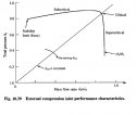
the picture says Fig 14 mach number distribution on a horizontal plane (parallel to X-Y plane) near design mass flow ratio and low flow ratio at Mach 1.7

of course you do not know the relation mass ratio pressure recovery
5943d1326099929-sdf-aerospace-aerodynamics-corner-mass-flow-rate2.jpg

5945d1326162081-sdf-aerospace-aerodynamics-corner-flowratiocapture2.jpg
 

Attachments

  • flowratiocapture2.jpg
    flowratiocapture2.jpg
    36.6 KB · Views: 49
Last edited:

Engineer

Major
you are incorrect simly for the following

A1 is free stream mass flow outside the intake or the potential capture flow stream, A0 is the actual flow stream entering the intake

If A1=A0 the rate is 1, however you have subcritical or supercritical states and the flow rate can be A0>A1 or A1>A0.

Second Air is spilled so you have an equation stablishing spill rate and spill.

Simply like that air is spilled like in a sink

and this proves my point

First, there is nothing incorrect about my statements. The fact that you are unable to pinpoint exactly what constitute as "incorrect" speaks volume. :rolleyes:

Secondly, air does not spill like water in a sink. Air is compressible, where as water is incompressible. This means your analogy is flawed and disproves your point. By Bernoulli's principle, the amount of air going through the inlet mouth is equate to the amount of air going through the inlet throat, and mass is conserved.
 

MiG-29

Banned Idiot
First, there is nothing incorrect about my statements. The fact that you are unable to pinpoint exactly what constitute as "incorrect" speaks volume. :rolleyes:

Secondly, air does not spill like water in a sink. Air is compressible, where as water is incompressible. This means your analogy is flawed and disproves your point. By Bernoulli's principle, the amount of air going through the inlet mouth is equate to the amount of air going through the inlet throat, and mass is conserved.

Bernoulli's principle also work for water and sinks overflow hahaha
 

Engineer

Major
As the SR-71 increases its speed, the inlet varies its exterior and interior geometry to keep the cone-shaped shock wave and the normal shock wave optimally positioned. Inlet geometry is altered when the spike retracts toward the engine, approximately 1.6 inches per 0.1 Mach. At Mach 3.2, with the spike fully aft, the air-stream-capture area has increased by 112 percent and the throat area has shrunk by 54 percent.
Please, Log in or Register to view URLs content!


and the same applies to a Mirage 2000 half cone intake as it applies to a SR-71 or MiG-21

Efficiency of the intake in all flight conditions is taken care
of by a variable-angle ramp in the upper surface of the intake
throat and by an auxiliary door in the floor of each intake.
The primary function of the ramp is to control the external
shock-wave pattern in front of the intake. The ramp is also
used to assist the lower surface auxiliary door when it is
necessary to spill air from the intake—for instance, when slow
engine failure occurs of there is a need to reduce excess thrust
Please, Log in or Register to view URLs content!

see they say primary function and the ramp also

Your citation says the following:
  • The intake ramp controls pattern of external shock wave;
  • Auxiliary doors (bypass) is used to dump air.

These are exactly what I have pointed out to you. The fact remains that intake ramp is used to control position of oblique shock waves, consequently causing change in throat area. However, the throat does not act as a valve to regulate flow, which is why bypass system must be installed.

At supersonic speeds, the hinged panels narrow down the throat area while diverting the excess airflow out of the ducts through aft-facing spill doors at the top of the intakes. At low speeds (especially during takeoff) when more engine air is needed, this airflow is reversed and extra air is sucked in via the spill doors
Please, Log in or Register to view URLs content!
This type of intake produces a series of mild shockwaves without excessively reducing the intake efficiency.12. As aircraft speed increases still further, so also does the intake compression ratio and, at high Mach numbers, it is necessary to have an air intake that has a variable throat area and spill valves to accommodate and control the changing volumes of air (fig. 23-9).The airflow velocities encountered in the higher speedrange of the aircraft are much higher than the enginecan efficiently use; therefore, the air velocity must be decreased between the intake and the engine air inlet.The angle of the variable throat area intake automatically varies with aircraft speed and positions the shockwave to decrease the air velocity at the engine inlet and maintain maximum pressure recovery within the inlet duct.

Please, Log in or Register to view URLs content!

This citation made the following points
  • Excess airflow flows out of the duct through spill doors;
  • Extra air flows in via spill doors;
  • Spill vales are needed to control changing volumes of air;
  • Angle of throat varies with aircraft speed to position shock waves that decrease air velocity flowing into the engine.

Once again, your citation makes the exact same points as I have. Bypass system is needed when there is a requirement to adjust the amount of air flowing into the engine. The variable-geometry does not serve this role. What the variable-geometry contributes is the adjustment of shock waves to maintain pressure recovery ratio.


look at the F-14 intake at max supersonic it is
Please, Log in or Register to view URLs content!

at subsonic speed
Please, Log in or Register to view URLs content!


Horizontal ramp inlet
– Fuselage boundary layer diverter required
– Long ramp lengths due to inlet aspect ratio (thicker
boundary layer)
Variable geometry capability in the ramp angle
changes for mass flow regulation
This is for F-14

Possible inclusion of variable cowl devices to enhance
inlet engine matching
F-15 case

sr-71 and Mirage 2000 do the same
Half cone inlet
– Variable geometry for mass flow regulation via translating
cone


this is for Mirage III/2000/kfir

The intake ramps shown in your pictures are for positioning of oblique shock waves. By Bernoulli's principle, the amount of air flowing into the inlet is the same as the amount of air flowing through the throat. Hence, adjustment of the amount of air going into the engine needs bypass system.

If you were right you only would need the by pass doors, not variable geometry throats, however the throat by changing its area also changes the amount of air ingested
Please, Log in or Register to view URLs content!

This is indeed the case, showing that I am right. Inlet only needs bypass doors, not variable-geometry throat. The inlet on F-18E does not have variable-geometry float. The inlet on F-22 does not have variable-geometry throat. On the other hand, variable-geometry inlet must incorporate bypass system, because the intake ramp does not regulate the amount of airflow as you claimed.
 

Engineer

Major
the picture says Fig 14 mach number distribution on a horizontal plane (parallel to X-Y plane) near design mass flow ratio and low flow ratio at Mach 1.7

of course you do not know the relation mass ratio pressure recovery
5943d1326099929-sdf-aerospace-aerodynamics-corner-mass-flow-rate2.jpg

5945d1326162081-sdf-aerospace-aerodynamics-corner-flowratiocapture2.jpg

Nope. The caption of the picture says "Mach number distribution on a horizontal plane (parallel to x-y plane) near design mass flow (left) and low mass flow ratio (right) at M∞ = 1.7." The paper clearly is talking about low mass flow ratio, and the flight condition is not subsonic speed unlike what you have claimed. This is evident in the following screen capture:
7UGKa.png


In the discussion of the right picture, the paper points out that pressure recovery ratio at sub-critical condition is higher than traditional inlet. This is because the oblique shock wave becomes stronger at high Mach number.
PetiV.png


The pressure recovery ratio of DSI at sub-critical condition is higher than traditional inlet. This is the finding of the paper:
ZxfTc.png


Please, Log in or Register to view URLs content!
 
Last edited:
Top