Naval missile guidance thread - SAM systems

Brumby

Major
I don't need to show you a product when talking about architecture. I think I've been quite thorough in illustrating the idea. I've shown you material that's used in radar education courses. The fact that you have such a difficulty understanding how an AESA can have a single transmitter tells me that you don't know what one is. Take a look again at those slides and find where the oscillator and modulator are. What do you think a transmitter transmits? Where does that come from?
When it is all said and done we are talking about a radar - the end product. Not TR architecture. In other words the subject is about radar and its performance specs. You build an end product for a purpose. Radar is a detection device and is governed by its signal energy equation. It can be expressed in many ways and the following are some of it.

1583883780505.png

Regardless of its expression, there is a common factor in all of them i.e. avg power of transmission. In AESA radar, the avg power is derived from the TR modules. The more you have the greater is the avg power (among other things). The aim of every AESA radar is to pack as many modules as possible in the design because ultimately that determines detection range. It would be totally moronic to build a single TR AESA because that would be counter to a good design. It is why there is none out there. Your continuing argument about a single TR design suggest you have no clue about overall AESA radar design.

You can't generate 10GHz coherent signal parallel in thousand(s) of emitters.

IT is extremely challenging even for 2 transmitter.
I have no clue what you are talking about or why it is even relevant. I suggest you provide a reference to a technical literature to back up what you are positing.
 

Tam

Brigadier
Registered Member
For me the question is the purpose of the DSPs in the modules.

Integer - float transformation ?
What else purpose can be there ?
anything the the DSPs doing needs to be done in perfect synchronous with others, so it can not be something that is not perfectly aligned with the other modules.

Is that a problem?

I can read very well, thank you. Unlike you, I am not re-interpreting what the author wrote. On the slide, it is clearly written "transmitter", not "transmitters". Singular not plural. What happened when moving from PESA to AESA is that one large HPA that was independent of an array got split into many small HPAs that were now made an integral part of an array. Still one transmitter, but many T/R elements. Transmitter ≠ T/R element. Still one receiver-exciter (REX) for both PESA and AESA in that slide. Still one wavefront transmitted by both radars.

It says transmitter distributed. You know what distributed means?

I see what the source of the confusion is. I am not saying that you can build an AESA with 1 TR element. That would not qualify as an array. Transmitter ≠ T/R element. I am saying that AESA can be built around one receiver-exciter (REX) unit and transmit one wavefront at a time. To transmit multiple wavefronts, you need multiple transmitters. Again, this is orthogonal to AESA/PESA. A MIMO radar is an example of a radar transmitting multiple wavefronts simultaneously.

There is an individual HPA behind each transmitter antenna on an AESA, and an individual LNA behind each receiver antenna on an AESA.

And there can be a signal generator behind each element. See below.

PESA shares the HPA and the LNA, and connects these to the array in long lines --- lines that are subject to conductive and thermal resistance, distortion from induction of nearby magnetic fields and so on. Magnetic fields like those from electric motors that rotate the antenna of BARS or Irbis.


A transmitter is a device that predates radar by many decades. Let's see what Wikipedia has to say about a transmitter: "The purpose of most transmitters is
Please, Log in or Register to view URLs content!
of information over a distance ... The transmitter combines the information signal to be carried with the radio frequency signal which generates the radio waves, which is called the
Please, Log in or Register to view URLs content!
. This process is called
Please, Log in or Register to view URLs content!
. "
According to Wikipedia, the components of a transmitter are:
- an electronic oscillator
- a modulator
- RF amplifier
- antenna tuner

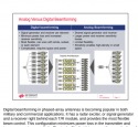
I'm going to re-post this beautiful AESA architecture drawing again:
View attachment 58186
See the two big blocks? One REX, multiple T/R modules. Analog outputs from the REX, analog input/outputs from the T/R modules. See which function the T/R module is performing? Sorry Tam, no FPGA in the T/R modules of this AESA. Also the signal is digitized "way back" from the antenna.


Way back, yeah right. Like you think the designers are idiots and are not aware of the need to keep the lines as short as possible.

Please, Log in or Register to view URLs content!


Screenshot 2020-03-11 at 1.56.38 PM - Edited.png

Oh it says exiter, signal generator and receiver is right behind each T/R module.

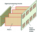
Do you see long lines there? In those particular kind of AESA, that does not use a QTRM, the FPGA and signal processing is in a PCB on the back of the TRMs.


469118_1_En_11_Fig5_HTML.png


unnamed.jpg
 

nlalyst

Junior Member
Registered Member
It would be totally moronic to build a single TR AESA because that would be counter to a good design. It is why there is none out there. Your continuing argument about a single TR design suggest you have no clue about overall AESA radar design.
I already told you that no one is saying you can or should build a single TR AESA. Not because that's a bad design, but because that is by definition not AESA. TR transmitter. 1 transmitter AESA OK. 1 TR AESA not OK.

The aim of every AESA radar is to pack as many modules as possible in the design because ultimately that determines detection range.
No, not really. Range is but one of the values of merit. If you are going to dumb things down all the way to this level, then the only conclusion we will ever come to is that bigger=better.
 

nlalyst

Junior Member
Registered Member
And there can be a signal generator behind each element. See below.
That is irrelevant when discussing what makes AESA different from PESA. The key phrase here is: can be. It's not a requirement for AESA. AESA can be fully analog from the signal generator to the antenna. That you can find dozens of examples that show a different design, does nothing to change that. In fact, the idea that you keep reposting is known as digital array radar (DAR). It's been a hot subject in the last 10 years. Yet, we've had functional AESA radars since the late 70s, when those ideas were little more than a pipe dream.

You strike me as a person who is in love with marketing. To you there is but one order relation: Digital > Analog. But when people ask you why, you go silent.

Way back, yeah right. Like you think the designers are idiots and are not aware of the need to keep the lines as short as possible.
Way back, as in the REX unit. The signal traversing that path to the TRMs is low power: it's amplified at the very last step, in the TRMs. The power loss due to distance is negligible compared to a PESA architecture.The point in that drawing was to show you the degree of analog processing that can take place in an AESA architecture. And to refute your claim that there can be nothing behind the phase shifters, but the antenna. It's also easy to go back to PESA in that drawing, but I leave that as an exercise to the reader. Do notice that the REX has a digital WFG and analog output. Another thing you said would not be possible on PESA.
 

nlalyst

Junior Member
Registered Member
To summarize again: the main difference between PESA and AESA is in where the high amplification step takes place. In AESA it is at the very end of the chain, after the phase shifters. In PESA it is before the phaseshifters.

Everything else: is the signal digital or analog, is the beamforming digital or analog, can it do LPI, does it have a FPGA or not, how many amplifiers are there, is irrelevant to the dichotomy of PESA vs AESA.
 

Tam

Brigadier
Registered Member
That is irrelevant when discussing what makes AESA different from PESA. The key phrase here is: can be. It's not a requirement for AESA.

Can be doesn't me They Do. Theoretical doesn't mean the Practical.

Go ahead and find me an AESA design that has long feed lines between the TRMs to the signal generators.


AESA can be fully analog from the signal generator to the antenna. That you can find dozens of examples that show a different design, does nothing to change that. In fact, the idea that you keep reposting is known as digital array radar (DAR). It's been a hot subject in the last 10 years. Yet, we've had functional AESA radars since the late 70s, when those ideas were little more than a pipe dream.

You strike me as a person who is in love with marketing. To you there is but one order relation: Digital > Analog. But when people ask you why, you go silent.

Except this signal generator is within the PCB or in a backplane orthogonal to the TRMs, which means a minimal length path.

Yes, Digital > Analog. Digital is binary, it is either 0 or 1. There is no distortion between the two. You honestly think that modern Telecom still uses any analog?

You strike me as a person who thinks designers are that stupid to go out of their way to deliberately design a bad design.

Way back, as in the REX unit. The signal traversing that path to the TRMs is low power: it's amplified at the very last step, in the TRMs. The power loss due to distance is negligible compared to a PESA architecture.The point in that drawing was to show you the degree of analog processing that can take place in an AESA architecture. And to refute your claim that there can be nothing behind the phase shifters, but the antenna. It's also easy to go back to PESA in that drawing, but I leave that as an exercise to the reader. Do notice that the REX has a digital WFG and analog output. Another thing you said would not be possible on PESA.

The amount of analog processing is irrevelant. You keep on focusing that. The LENGTH of the analog feed lines. Don't you get it? The physical length of these lines that cause signal distortion and loss. Long physical feed lines that PESA has and AESA doesn't. Something that has been made clear to you diagram after diagram after diagram.

You are really full of sh*t focusing on what's not important, vs. to what's really important.
 

Tam

Brigadier
Registered Member
To summarize again: the main difference between PESA and AESA is in where the high amplification step takes place. In AESA it is at the very end of the chain, after the phase shifters. In PESA it is before the phaseshifters.

Everything else: is the signal digital or analog, is the beamforming digital or analog, can it do LPI, does it have a FPGA or not, how many amplifiers are there, is irrelevant to the dichotomy of PESA vs AESA.

What???

The main difference of PESA and AESA is that PESA has a centralized amplification unit way back of the phase array, where AESA uses distributed micro-amplification units that reside under the transmitters and receivers. In AESA you can still have waveguide type phase shifters which means the HPA would have to be behind it so the relative location of the phase shifter doesn't matter. Centralization of amplification vs. Distribution of amplification. This goes both in the transmit and receive end.

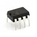
The others are universal to all radars, but with AESA, you can put these components much closer to the array face in a highly micro and distributed manner, for much of the same reasons why you can put button small HPA and LNA very close to the face. While they are not part of what defines an AESA over a PESA, the distribution of these other components and relocation close to the array face is one of AESA's collateral benefits and attributes. Here is an A/D converter by the way. What's the point of putting these in the back when you can put them under the face now?

08636-03-L.jpg

That means A/D and D/A conversion and digital beamforming can be performed much closer to the array face. As for LPI, this works against large centralized high power amplifiers due to them working at high power. LPI requires the radar work at very low power levels that the signal has the same amplitude as the noise. That favors tiny amps. This works better with a radar that has a very high receive gain, and with the LNA and A/D close to the face, so the faint returns do not get distorted or lost easily transiting from the array to the main receiver.

Furthermore, AESA can perform down to the subarray level, allowing each subarray to perform like a separate radar on its own.

The mass industrialization of miniaturized components make AESA the logical way to construct phase arrays in this time and age.
 

nlalyst

Junior Member
Registered Member
Can be doesn't me They Do. Theoretical doesn't mean the Practical.

Go ahead and find me an AESA design that has long feed lines between the TRMs to the signal generators.
That diagram comes from NXP. It posted it to show that you were wrong about the phaseshifter placement in AESA.

Yes, Digital > Analog. Digital is binary, it is either 0 or 1. There is no distortion between the two. You honestly think that modern Telecom still uses any analog?

Except when you can't build your receiver to handle ultrawide bandwidth at X-band and above. So you in your digital camp will have nothing, while I will have a functional analog device. Yes, digital is making great progress, but sometimes we need to make do with what we have at the moment.

The amount of analog processing is irrevelant. You keep on focusing that. The LENGTH of the analog feed lines. Don't you get it? The physical length of these lines that cause signal distortion and loss. Long physical feed lines that PESA has and AESA doesn't. Something that has been made clear to you diagram after diagram after diagram.

You are really full of sh*t focusing on what's not important, vs. to what's really important.
I am done with the topic of AESA vs PESA. I already repeated far too many times what the actual difference is.

This discussion about analog vs digital, and signal path length while interesting is largely orthogonal to array architecture. You can apply all of that to MIMO as well.
 

nlalyst

Junior Member
Registered Member
What???

The main difference of PESA and AESA is that PESA has a centralized amplification unit way back of the phase array, where AESA uses distributed micro-amplification units that reside under the transmitters and receivers. In AESA you can still have waveguide type phase shifters which means the HPA would have to be behind it so the relative location of the phase shifter doesn't matter. Centralization of amplification vs. Distribution of amplification. This goes both in the transmit and receive end.
Why would you want to put the phaseshifter after the HPA?

Also, the facts don't bear out your claims. We've already identified two PESA radars, that don't have a central amplifier. SPY-1A has 32 amps, each handling a subarray of say 128 elements. Thereby, there is no single high power hotspot in the architecture and even if a few amps die, the system will gracefully degrade, instead of blackout.
 
Top