SinoSoldier
Colonel
The engine shielding from the sides is quite poor, at least compared to the F-35.
Low quality comment. If they wanted to extend some flaps to cover more, they could easily. They chose not to for a reason.The engine shielding from the sides is quite poor, at least compared to the F-35.
Low quality comment. If they wanted to extend some flaps to cover more, they could easily. They chose not to for a reason.
why? it isn't real as in made by anyone related to PLA.
No point to comment, it isn't real.Top one has the PLAAF emblem. The other two are PLAN.

Are you sure you are comparing the real airframe of FC-31 (J-35) with F-35? And what observation exactly made you reach your conclusion? An one line assertion without acompanying reasoning is very low quality post.The engine shielding from the sides is quite poor, at least compared to the F-35.
Wasn't implying that it was an oversight or technical deficiency. The observation stands, whether it be unintended or something that was sacrificed for another technical advantage.
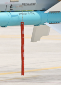
Kind of off topic but interesting seeing PL-8 training aide on a PF10.why? it isn't real as in made by anyone related to PLA.
No point to comment, it isn't real.
First of all, why English? PLA isn't made of English speakers. Secondly, there is similar real items photographed. In Chinese "起飞前卸下", literally "Remove before flight".
View attachment 138059
There's very little going on back there that would be compromised by rear flaps to cover the sides of the engines. Your observation is based on eyeballing. The design was based on thorough thermodynamic studies of the engine and the petal materials as well as the movement/dissipation of the heat in relation to the airflow of the jet while it is flying. They likely covered up what was identified as a risk and left open what they determined to be safe, even if it appears to an untrained eye that they could have hidden the engine much more.Wasn't implying that it was an oversight or technical deficiency. The observation stands, whether it be unintended or something that was sacrificed for another technical advantage.
Wasn't implying that it was an oversight or technical deficiency. The observation stands, whether it be unintended or something that was sacrificed for another technical advantage.
Interestingly enough, with the recent official release of air force variant J-35 photo (the closeup one with the vertical tail) and what we previously had regarding the naval variant, these key-fobs did a surprisingly good job regarding the details. Note that the control surfaces are different between the variants, which is consistent with the actual aircrafts and, in the case of the air force variant, shows correct detail that was unavailable to the general public at the time that these key-fobs were made. (That is, unless we have previously had good quality photos of the air force variant that I was not aware of that made the vertical tail control surface design public knowledge)
Oh Liaoning already changed the wheel chocks? Do you have a picture? I couldn't tell when I checked with Liaoning's dual carrier op pics
Speaking of which, an update:
Roughly translated:
Have a closer look at the older wheel chock:
View attachment 127552
And compare it with the newer wheel chock:
View attachment 127553
The older wheel chocks have 11 "blades", while the newer wheel chocks have 14 "blades". Also, the widening of the wheel chocks involved adding additional "blades" inwards (i.e. towards the center).
On one hand, this should confirm that the J-35s is indeed STOBAR-capable and will be capable of operating from Liaoning (and Shandong after her mid-life upgrade sometime in the future).
On the other hand, comparing the newer, wider wheel chocks at the PLAN NAU to the even wider wheel chocks on the Kuznetsov CV:
View attachment 127554
We can see that while each of the twin wheel chocks on the Kuznetsov are divided into two halves with 11 "blades" on each halves (i.e. 22 "blades" in total), such that the outer halves are used for the SU-33 while the inner halves are used for the MiG-29K - The newer, wider wheel chocks at the PLAN NAU are operated as a whole.
This should mean that spacing between the rear undercarriages of the J-35 is pretty wide. Not as wide as the J-15, but certainly nowhere as narrow as the MiG-29K.
Original video segment of the wheel chocks:
@Deino @Blitzo FYA.
