Design a warship fun thread

proelite

Junior Member
Curious with no angle deck. As someone that actually worked on the flight deck on three USN CVs I think without an angle deck so when aircraft bolter there's a possibility of aircrfat veering off course and striking flight deck personnel and damaging and or destroying aircraft. However on this ship the number of aircraft is small so the possibility of those type crashes is diminished.

Should the barrier help with bolters during simultaneous launching and landing?
 

bd popeye

The Last Jedi
VIP Professional
Should the barrier help with bolters during simultaneous launching and landing?

Sure..but it's best to have an angle deck so those bolters just pass on by. I guess you can always spot the recovered aircrfat on the starboard side of the ship.

Bolter...


some of these are touch and goes. If the tail hook is not deployed that is a touch and go.
 

Totoro

Major
VIP Professional
Proelite, I commend you for your effort. It takes time to draw something, and it shows perseverance when you update the designs.

May I ask, how long did it take you to make that 3d model? Was it made with SketchUp? If you have no serious previous experience with 3d modelling software, a model like that must've taken you 5+ hours to make.

Anyway, onto the concept itself. Why such a short carrier? I too invested quite a bit of time in carrier concepts and came to the conclusion that length usually trumps width. you can get a more efficient design with a longer deck than with a wider deck, if actual deck area is the same. Wide deck usually means wide hull, or at least a lot of support for that wide hull, meaning a lot of excessive weight. And wide hull and extra weight usually slow the ship down. Meaning it needs to use more powerful propulsion.

Island seems too far aft, in my opinion. While IEP does allow more leeway when it comes to positioning the turbines, they still should be positioned fairly close to the centre of the mass of the ship. They're very unlikely to be able to be that far aft, inside the ship. And having them more to the front, yet having the island with the exhaust/intake so far back means there would have to be way too much volume consuming piping going through the ship. It's also make the ship less structurally sound. It's add extra weight. Absolutely majority of ships designs (including carrier) feature exhausts/intakes with almost-shortest possible route up, without too much piping.

Why two big turbines? QE carrier, which is more than double the displacement, uses that many. Then again, you didn't clearly show the hull form. If very wide, it very well might need that much power. Why four props though? QE does just fine with two screws. Only the huge US designs, over 3 times more than your displacement, have four screws. It doesn't seem very efficient, adding unnecessary weight. Anyway, if we are talking about two mt30 turbines, then the island is too small. It barely has enough room for feeding air and providing exhaust for one turbine. And when one deducts the intake/exhaust needs, the remainder of the island is also too small. There's a need for multiple bridges on it, facing all sides. Ford carrier, which has basically the smallest island one could get away with, requires 25 by 12 or so meters. Without intakes/exhausts. I would thus suggest 25 by 20 meters or 30 by 16 meters or something like that, if you're to fit two sets of turbines in it.

There's some other stuff one could critique but I won't go into such details...

Anyway, it's a good try, though a bit unrealistic.
 

proelite

Junior Member
Proelite, I commend you for your effort. It takes time to draw something, and it shows perseverance when you update the designs.

May I ask, how long did it take you to make that 3d model? Was it made with SketchUp? If you have no serious previous experience with 3d modelling software, a model like that must've taken you 5+ hours to make.

Anyway, onto the concept itself. Why such a short carrier? I too invested quite a bit of time in carrier concepts and came to the conclusion that length usually trumps width. you can get a more efficient design with a longer deck than with a wider deck, if actual deck area is the same. Wide deck usually means wide hull, or at least a lot of support for that wide hull, meaning a lot of excessive weight. And wide hull and extra weight usually slow the ship down. Meaning it needs to use more powerful propulsion.

Island seems too far aft, in my opinion. While IEP does allow more leeway when it comes to positioning the turbines, they still should be positioned fairly close to the centre of the mass of the ship. They're very unlikely to be able to be that far aft, inside the ship. And having them more to the front, yet having the island with the exhaust/intake so far back means there would have to be way too much volume consuming piping going through the ship. It's also make the ship less structurally sound. It's add extra weight. Absolutely majority of ships designs (including carrier) feature exhausts/intakes with almost-shortest possible route up, without too much piping.

Why two big turbines? QE carrier, which is more than double the displacement, uses that many. Then again, you didn't clearly show the hull form. If very wide, it very well might need that much power. Why four props though? QE does just fine with two screws. Only the huge US designs, over 3 times more than your displacement, have four screws. It doesn't seem very efficient, adding unnecessary weight. Anyway, if we are talking about two mt30 turbines, then the island is too small. It barely has enough room for feeding air and providing exhaust for one turbine. And when one deducts the intake/exhaust needs, the remainder of the island is also too small. There's a need for multiple bridges on it, facing all sides. Ford carrier, which has basically the smallest island one could get away with, requires 25 by 12 or so meters. Without intakes/exhausts. I would thus suggest 25 by 20 meters or 30 by 16 meters or something like that, if you're to fit two sets of turbines in it.

There's some other stuff one could critique but I won't go into such details...

Anyway, it's a good try, though a bit unrealistic.
Hi Totoro,

thanks for your writeup. I made the first image using a combination of ms paint and gimp. The shafts are actually lifted from an image of the Gerald Ford. They've being causing quiet a bit of confusion. I have no knowledge of ship design and carrier design so I am just getting educated on them based on feedback. I would make them 2 shafts instead.

I wanted to challenge myself into making a carrier as small as possible so I wanted to get rid of what I had imagined was wasted deck space in the Charles DeGualle's area right of its fore cat.

The waterline beam is actually only around 100 feet. A 6.8 to 1 ratio for length to beam is actually workable based on my research.

If the funnel in the island is causing piping problems can I position funnels sideways like the ones on WW2 carriers ala Akagi?
 

proelite

Junior Member
I also understand that carriers are better if bigger, this was a thought experiment purely based on extreme minimalism. For me the extremes are the most interesting to consider. Either extremely large or extremely small.

I am also thinking about a 120k ton 1200 feet over-compensating design for the Chinese Type 005 supercarrier with over 100 planes complement!
 

bd popeye

The Last Jedi
VIP Professional
Why two big turbines?

One reason could be that the ship has a back up if one of those turbines fail. With only one turbine and if it fails the ship is dead in the water. Warships need to keep moving in time of battle and other circumstances.

I wanted to challenge myself into making a carrier as small as possible so I wanted to get rid of what I had imagined was wasted deck space in the Charles DeGualle's area right of its fore cat.

Fore cat? I'm missing something here. Do you mean the forward catapult? I just want to be sure. Thanks!
 
Last edited:

gelgoog

Lieutenant General
Registered Member
...

I wanted to challenge myself into making a carrier as small as possible so I wanted to get rid of what I had imagined was wasted deck space in the Charles DeGualle's area right of its fore cat.

The waterline beam is actually only around 100 feet. A 6.8 to 1 ratio for length to beam is actually workable based on my research.

If the funnel in the island is causing piping problems can I position funnels sideways like the ones on WW2 carriers ala Akagi?

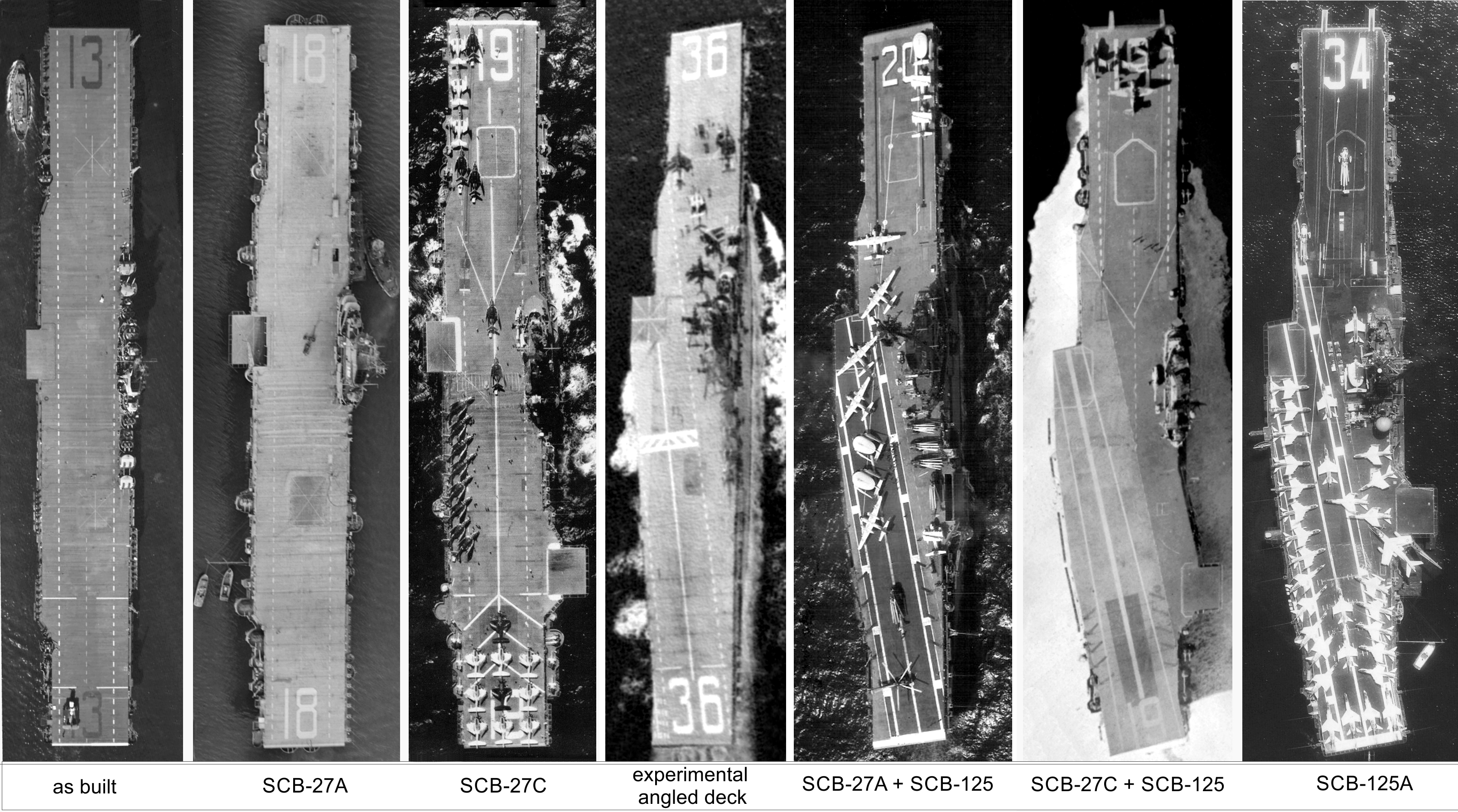
I have always found the evolution in US carrier design since WW2 quite interesting. This is one example of a class which served from 1944 to 1991. The Essex-class through its many modernizations.

Essex-class_carrier_modernisations_1944-1960.jpg
 

proelite

Junior Member
One reason could be that the ship has a back up if one of those turbines fail. With only one turbine and if it fails the ship is dead in the water. Warships need to keep moving in time of battle and other circumstances.


Fore cat? I'm missing something here. Do you mean the forward catapult? I just want to be sure. Thanks!

Fore cat is the forward catapult.
 
Top