Chinese AEGIS capability and comparison

Tam

Brigadier
Registered Member
This part here describes HHQ-9's guidance, and divides into Passive and Active. Passive here sounds like typical inertial guidance with datalink update or command guidance. The missile then transitions to active homing state.

In September, President Hua (Haigen Hua), Wang Jun and I went to the 8th Academy of the Ministry of Aerospace (Missile General) of the Ministry of Aerospace in Shanghai to ask about missile guidance modes and other issues. President Hua has done target testing with the experts of the institute and has a good relationship with the leaders of the institute. We asked them a lot of missile issues as students. Long-range missile strikes are divided into two stages, passive guidance and active guidance. In the passive guidance section, after the missile is launched, it is tracked by radar and sends correction instructions to guide the missile to the target. The active guidance section is when the missile approaches the target and turns on the active homing function to automatically seek and hit the target. The purpose of our research is to know how long the missile can be actively guided? What is the power and sensitivity of the response antenna on the missile? And what is the orbit of the missile launch section? The signal receiving direction of the response antenna on the missile, the accuracy requirements of the passive guidance terminal missile and the target, and the actual data of the reflection cross-sectional area of the missile's head, tail, and sides in various directions, etc.

In the passive or midphase command guidance state, there is an issue with the missile's tail radar cross section, which if its too low will give trouble. The radar still has to be able to track the missile and send instructions to it.

Author wasn't happy when Institute 23 did not furnish the correct data on the missile's tail radar cross section which turned out to be smaller than the head.

In July and August of 1993, Nanjing was as hot as a stove. The 14th institute first had a half-day shift. By the end of July and early August, there were about two weeks of non-working all day. And I spent morning to night in the computer room to study, calculate and simulate the low-angle tracking performance of the S-band phased array radar, and find ways to improve its performance. At the same time, it also cooperated with Nanjing University of Aeronautics and Astronautics and asked them to help simulate the reflection cross-sectional area of the HH-9 missile at various angles. We can't believe that the 23rd Institute of the Ministry of Space and Space has spoken out!
There is air conditioning in the computer room, and the high temperature outside the computer room exceeds 36 degrees. People are very susceptible to colds as soon as they enter and exit. I was taking cold medicine, and I insisted on fighting in the computer room alone. At home, my daughter was lying on the bed due to a fractured bone and was taken care of by my in-laws. (I feel guilty about my daughter so far. She has graduated from Harvard Ph.D. I see the scar on her foot, I will feel heartache). Hard work pays off. In two months, I found some ways to improve the radar's low-angle tracking performance by using the characteristics of active arrays (the article was later published in "Modern Radar"); at the same time, I went to Nanjing University of Science and Technology to find a radar theory expert ( Such as Professor Liu Guosui) and PhD students discussed the solution together, and they later published several papers in this area. At the same time, the experts of China Southern Airlines also helped us to simulate the reflection cross-sectional area of the HH-9 missile at various angles. It can be seen that the reflection cross-sectional area data given by 23 of the Second Academy of the Ministry of Aerospace Industry is problematic. The most obvious problem is that they said that the reflection cross-sectional area of the missile tail is smaller than the reflection cross-sectional area of the missile head.
In September, President Hua (Haigen Hua), Wang Jun and I went to the 8th Academy of the Ministry of Aerospace (Missile General) of the Ministry of Aerospace in Shanghai to ask about missile guidance modes and other issues. President Hua has done target testing with the experts of the institute and has a good relationship with the leaders of the institute. We asked them a lot of missile issues as students. Long-range missile strikes are divided into two stages, passive guidance and active guidance. In the passive guidance section, after the missile is launched, it is tracked by radar and sends correction instructions to guide the missile to the target. The active guidance section is when the missile approaches the target and turns on the active homing function to automatically seek and hit the target. The purpose of our research is to know how long the missile can be actively guided? What is the power and sensitivity of the response antenna on the missile? And what is the orbit of the missile launch section? The signal receiving direction of the response antenna on the missile, the accuracy requirements of the passive guidance terminal missile and the target, and the actual data of the reflection cross-sectional area of the missile's head, tail, and sides in various directions, etc.
 
Last edited:

nlalyst

Junior Member
Registered Member
This is followed by this:This sounds to me a rather typical QTRM meant to cut down size and weight, with the entire QTRM around 100W combined peak power. Each QTRM has four T/Rs. So each HPA peaks around 25W.
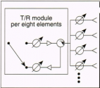
Yeah, it does sound like that. I was suspecting that cost may have been the driver in adopting the quad-pack where each TRM drives several elements as in this schematic:
QTR.png
Too bad we don't have any official information. I would like to know the cost of that setup, especially compared to other alternatives.

In the early 90s, the USN pursued hybrid arrays where the center part was an AESA built with 1:1 mapping of T/R to radiators/receivers and the outer part a PESA with a subarray arrangement as in the above schematic. This because even for them it was too expensive to build a full AESA the size of SPY-1 arrays.
 

Tam

Brigadier
Registered Member
Yeah, it does sound like that. I was suspecting that cost may have been the driver in adopting the quad-pack where each TRM drives several elements as in this schematic:
View attachment 66848
Too bad we don't have any official information. I would like to know the cost of that setup, especially compared to other alternatives.

In the early 90s, the USN pursued hybrid arrays where the center part was an AESA built with 1:1 mapping of T/R to radiators/receivers and the outer part a PESA with a subarray arrangement as in the above schematic. This because even for them it was too expensive to build a full AESA the size of SPY-1 arrays.

The way he describes it here as

"Here, I will explain the T/R components: T/R components are transceiver components (T-Transmitter, R-Receiver), each component includes antenna, transmitting module, receiving module, circulator, transceiver switch, and phase shifter Wait. It can be said that each T/R component is a small radar.
T/R components are the key components of solid-state active arrays. "Solid state" means that the emitting tube is a solid-state transistor (long life and high reliability), and "active array" means that the emitting tube is on the front (small emission loss and high efficiency). The use of T/R components not only greatly reduces transmission and reception losses and improves power efficiency, but also greatly improves the reliability and maintainability of the front. It is the most advanced radar technology in the world.
The solid-state active phased array scheme adopted in 14 is that each antenna unit corresponds to a T/R component, and 4768 antenna units in each array correspond to 4768 T/R components. The ship is placed at an angle of 90 degrees. To cover a 360-degree orientation, a total of 19,000 T/R components are required. The most advanced phased array solution of solid-state active array is characterized by"

Its a one antenna, one T/R. Not four antennas to one T/R.

"In order to reduce the volume and weight, we adopted a 4-unit T/R module solution consisting of 4 units. According to the wavelength requirements, it must be within a volume of 20cm wide, 5cm thick, and 45cm long, and arranged in 4 T/R modules that can work independently. "

My bold.

Each small antenna element has its own T/R, and 4 T/Rs in a single board, sharing the same packaging and power supply. Its 4 T/Rs sharing a single board, not four elements sharing a single T/R. Each individual element has its own T/R, so each board has four antennas, four circulators, four HPAs and four LNAs, but sharing the same packaging and power supply, with the combined power consumption of the four T/Rs is around 100w, not the combined radiating power of four elements.

QTRM arrangement is common in aerial AESA like in fighter jets to reduce weight and space requirements.

If you read the rest of the article --- its better than any official source, I consider it the Rosetta Stone when it comes to understanding the Type 346 and HHQ-9 operation --- there are weight and power issues given the limitations in the potential of the 052 hull platform.
 
Last edited:

nlalyst

Junior Member
Registered Member
If you read the rest of the article --- its better than any official source, I consider it the Rosetta Stone when it comes to understanding the Type 346 and HHQ-9 operation --- there are weight and power issues given the limitations in the potential of the 052 hull platform.
Indeed, it is a treasure trove of information. Extremely unusual given the general paucity of data on PLAN systems. However, as a natural skeptic I accept it with a grain of salt.

From reading the transcript, the author appeared somewhat jaded or frustrated with the lack of recognition his work received in China. Perhaps that was the reason why he came out with all this data after he and his family emigrated to Canada? It will be interesting to see in retrospect how much of that was true one day the PLAN decides to divulge the data on the radar.

Now that you mention weight, that's another item from the Wikipedia page that appears fishy. He mentioned the upper acceptable limit of 4t per array front. That doesn't imply that the total topside weight of the radar system is <16t. The much smaller Dutch APAR has a total weight of 20t, half of which topside, with about 2t per array. In comparison, the Type 346 array faces appear unusually light for their size. Maybe that explains their relatively low power output, which didn't require liquid cooling and heavy heatsinks? Each APAR face dissipates 85kW of heat.
 

Tam

Brigadier
Registered Member
Indeed, it is a treasure trove of information. Extremely unusual given the general paucity of data on PLAN systems. However, as a natural skeptic I accept it with a grain of salt.

From reading the transcript, the author appeared somewhat jaded or frustrated with the lack of recognition his work received in China. Perhaps that was the reason why he came out with all this data after he and his family emigrated to Canada? It will be interesting to see in retrospect how much of that was true one day the PLAN decides to divulge the data on the radar.

Now that you mention weight, that's another item from the Wikipedia page that appears fishy. He mentioned the upper acceptable limit of 4t per array front. That doesn't imply that the total topside weight of the radar system is <16t. The much smaller Dutch APAR has a total weight of 20t, half of which topside, with about 2t per array. In comparison, the Type 346 array faces appear unusually light for their size. Maybe that explains their relatively low power output, which didn't require liquid cooling and heavy heatsinks? Each APAR face dissipates 85kW of heat.

He describes the system as air cooled, which explains the curvature of the face. There is more heat radiated at the center of the array and so more air is needed at the center, resulting in the curvature. However curvature does increase the RCS of the face and its susceptibility to battle damage, hence going with liquid cooling and a flat face in the 052D.

APAR is X-band vs. S-band for the Type 346. As such on X-band, the elements are much more closer to each other based on just about half the wavelength used between elements. A 10cm S-band wavelength means a little over 5cm spacing between elements but a 3cm X-band wavelength means a little over 1.5cm. So the X-band array is much more denser, for the same number of elements. This means more ingenious cooling solutions and module packaging are needed for the X-band, hence like QTRMs and even beyond that. This is a bit of apples vs. oranges comparison here, its better to compare APAR with another X-band AESA. Due to the higher attenuation with higher frequencies, you are going to have to pump more power to the TX to compensate to get the range you wanted, so the higher frequency radar is forced to run hotter.

The author does describe the competitor to the S-band Type 346 as one running with the shorter C-band, and with that, they are getting less than half the range of the S-band array. The limitations of the ship's power, cooling and top weight, makes it impossible to grow a C-band array to attain the near 300km ranges needed, which will definitely require far more than the 4700+ elements per array face.
 

nlalyst

Junior Member
Registered Member
APAR is X-band vs. S-band for the Type 346. As such on X-band, the elements are much more closer to each other based on just about half the wavelength used between elements. A 10cm S-band wavelength means a little over 5cm spacing between elements but a 3cm X-band wavelength means a little over 1.5cm. So the X-band array is much more denser, for the same number of elements. This means more ingenious cooling solutions and module packaging are needed for the X-band, hence like QTRMs and even beyond that. This is a bit of apples vs. oranges comparison here, its better to compare APAR with another X-band AESA.
That's a good point.

This
Please, Log in or Register to view URLs content!
has some data on SPY-4, which is of comparable size to Type 346 (and SPY-1). It states a weight of 22,500 pounds, or roughly 10t per array. This is 9,500 lbs more than the SPY-1 face. No wonder they had to strengthen the Arleigh Burke hull to accommodate the even larger SPY-6.

One very interesting detail that has not been revealed by the esteemed scientist is the tunable bandwidth of the Type 346 radar. I am thinking that there have been some major improvements in the latest variant onboard the Type 055, because it ditched the L-band surveillance radar found on Type 052C/D. Could it be that it can now radiate in L-band ?
 

Tam

Brigadier
Registered Member
That's a good point.

This
Please, Log in or Register to view URLs content!
has some data on SPY-4, which is of comparable size to Type 346 (and SPY-1). It states a weight of 22,500 pounds, or roughly 10t per array. This is 9,500 lbs more than the SPY-1 face. No wonder they had to strengthen the Arleigh Burke hull to accommodate the even larger SPY-6.

One very interesting detail that has not been revealed by the esteemed scientist is the tunable bandwidth of the Type 346 radar. I am thinking that there have been some major improvements in the latest variant onboard the Type 055, because it ditched the L-band surveillance radar found on Type 052C/D. Could it be that it can now radiate in L-band ?

The one on the 055 is even bigger than the previous two (or two and a half, as the second block of 052D is another variant.) One Chinese journalist says the radar use Gallium Nitride. The 055 does seem to have more power with four gas turbines and six generators. Another thing to note is that the ship appears to continually belch a lot of water at the hull, so it does seem to be cooling a lot inside the hull.

I think the one on the 055 is a continued evolution. Assuming the same wavelength are used, it may have more elements than the 346A, and more power to each element. And that's not all. There is a second set of AESA on its mast, a new set. This one might be an X-band, considering the absence of the X-band mechanical fire control radars used with previous ships, the new X-band AESA replaced these mechanical radars and should use the same bands. The ship also has a huge ECM panel along the sides which may also be a phase array. There is little information about the new features of the 055 up to now, but I will consider the possibility that both S and X-band AESAs may work in a coordinated dual band approach.

The total number of Type 346 variants are actually six:

Type 346 on the 052C.
Type 346 variant on the Liaoning.
Type 346A on the 052D.
Type 346A variant on the Shandong.
Type 346A improved variant on the second and third batch of 052D. This loses the external near field calibration probe for an internal method of calibration.
Type 346B variant on the 055.

The carrier variants no longer have the C-band communication arrays for the HHQ-9, so they can devote more of the extra array face for additional S-band elements.

Upcoming Type 003 carrier will feature its own Type 346B variant.
 

nlalyst

Junior Member
Registered Member
I think the one on the 055 is a continued evolution. Assuming the same wavelength are used, it may have more elements than the 346A, and more power to each element.
My thinking was that they may have expanded the tunable bandwidth to include both S-band and L-band, like some other radars. But I just now realized that the Type 517B is a A-band or VHF radar. VHF would almost certainly be beyond the tunable range of a S-band radar, as that's 10 octaves.
 
Last edited:

Tam

Brigadier
Registered Member
My thinking was that they may have expanded the tunable bandwidth to include both S-band and L-band, like some other radars. But I just now realized that the Type 517B is a A-band or VHF radar. VHF would almost certainly be beyond the tunable range of a S-band radar, as that's 10 octaves.

L-band alone would require doubling of the physical spacing between elements. With S-band from 3.75cm to 7.5cm, L-band would be 7.5cm to 15cm. The other problem is that the radars are not for search and detection only. They need it to track the HHQ-9 missile itself simultaneously with the targets, and this information is used for command guidance of the missile. A shorter wavelength helps them do that for more precise tracking and angular resolution. Changing to a longer frequency is going to mess up all the calculations they have carefully established all through these years to sufficiently track the missile within the required accuracy parameters. Fair to say, they have already struck a balance between their range and tracking requirements and they are not going to mess these things up. There are other ways to increase range. One of course is more power. Another way is to have a larger array with more elements for better receive gain and this array already looks bigger than its predecessors. You can improve the individual sensitivity of each element. You can go with a longer PRF with pulse compression.
 

nlalyst

Junior Member
Registered Member
L-band alone would require doubling of the physical spacing between elements. With S-band from 3.75cm to 7.5cm, L-band would be 7.5cm to 15cm. The other problem is that the radars are not for search and detection only. They need it to track the HHQ-9 missile itself simultaneously with the targets, and this information is used for command guidance of the missile. A shorter wavelength helps them do that for more precise tracking and angular resolution. Changing to a longer frequency is going to mess up all the calculations they have carefully established all through these years to sufficiently track the missile within the required accuracy parameters...
Not like that. I was speculating that the new radar might be able to operate both in S-band and L-band. Thereby it would be fully backwards compatible with HHQ-9 and gain additional capability against VLO and ballistic missiles.
 
Top