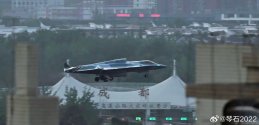
Chengdu next gen combat aircraft (?J-36) thread

AssassinsMace

Lieutenant General
How about it's a multirole aircraft? When it's in A2A beast mode and flying at an altitude where most missiles won't be able to touch it, you think it needs to dogfight? As I heard one US military YouTube channel say and not about the J-36 or any other Chinese aircraft, he said anytime you end up in a dogfight, it means all your main defenses have failed. This beast and it will be a beast in any role will be raining down hell on anything below it. Just look at what Pakistan was able to do. China has its own web kill chain that the US has experienced already.

Now we're back to A2A as being most desirable after Americans were self-stimulating on the multirole F-35. "The J-36 don't look like a fighter...!" You know why the usual suspects think the J-36 and J-50 look ugly to them? It's because they can't say it looks like an F-22 or F-35. In other words they can't take credit claiming it was stolen. They're designs they didn't come up with. Those wing-tip rudders on the J-50, it totally perplexes them. Yeah in other words since they don't have them on their fighters, how can it possibly work?
 

mond

New Member
Registered Member
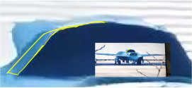
Actually there behind the intake itself there is a hump before it depresses downwards, highlighted in yellow

View attachment 153825

Viewed from our angle, but on the opposite side of the aircraft, it is highlighted and seen as below

View attachment 153826
Notice in the lower image how the highlighted portion is almost as long as the IWB main door, in perspective. The IWB is known to stretch across around a third of the plane. But this hump is less than a tenth.

Specifically from the side profile illustration (first quoted image), I measure the actual length of the highlighted hump to be 41px/577px ~= 7%, including the forward-swept cowl. If I just measure the length starting from the connection to the fuselage, I get half of that, 20px or 3.5%.

In the second quoted image, however, I measure a (47px, 11px) diagonal which has length 48.2 px for the bump in yellow along where it attaches to the fuselage. The main bay door is ||(56, 15)|| = 57.9 px, and the side bay door is ||(39, 11)|| = 40.5 px. So, the actual ratio is 48/58 = 0.83, whereas it should be 0.1. This is nearly an order of magnitude difference.

Even if there was significant widening of the intake manifold so that it was at a slight angle, say the intake widens at around 20º from the central axis of the plane (a lot! would be hella drag), we would only expect a factor of sin(140º)/sin(160º) ~= two increase to at most a ratio of 0.2 relative to the main IWB bay door from this perspective, which is still a factor of 4 away from what is illustrated! This is to say that this theory for the hump is just not plausible.

I'm outlining a more reasonable estimate of what the yellow region should really look like below -- you can actually see a sort of "humped" portion if you zoom in very closely. This measures (8px, 4px) which is about 9px across, which is far more reasonable, but possibly still a bit of an overestimate (1.5x what it should be in an ideal case, but could be explained by a slight widening of ~10 degrees).
Screenshot 2025-06-07 at 9.50.14 PM.png

I don't think that's the case, because a depression of the dorsal intake/fuselage when looked at from this frontal offset angle would not directly visually "travel" to the exhaust like that. Instead it would be mostly wholly obscured from this angle. I.e. it "should" look more like a hump from this angle rather than a direct, highly angled drop.
The reason the drop is so exaggerated from this angle is because the central intake tapers down and in towards the exhaust. It is not only not level, but also tapers inward a bit, since the intake is quite wide, wider than the exhausts -- we know this because the intake is already much more than a third of the width of the fuselage at this angle, while the exhausts are equal in size. At a nearly head-on angle, the foreshortening will make it appear like a sudden drop. I believe this is illustrated the best with the line connecting from the top left corner of the intake to the top left corner of the exhaust. You can see that, even with significant play in where the central exhaust actually ends up, the line drawn makes it clear that the intake manifold should cut well inside of the silhouette you have drawn in red.

1749317747865.png

The CG in #3318 is from a slightly higher-up and more side-on position, but you can see how quickly the manifold drops down and that it does not extend all the way to the left engine hump. In #3317 you can see how the side profile is accurate to previous observations, including the side-on images we have been discussing. Note especially the "groove" between the nacelles!.

The left exhaust is not actually "jutting out" -- that's because we cannot actually see the rear of the aircraft from this angle.
The entire rear of the aircraft, either due to photo resolution issues or AI post processing, is basically fully gone.
I don't think we have any reason to believe so. It is not typical for AI post processing, which largely consists of sharpening and other convolutions, to erase parts of an image as you describe. There is nothing as far as I can tell that is supposed to be there that isn't, the hump from the S-duct of the intakes block the exhaust from direct view, as expected -- please correct me if I am mistaken. Even if it were the case, it would not invalidate any previous statements.

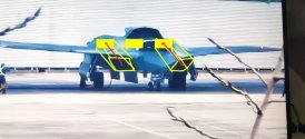
However, I positioned the left and right exhausts where they would be at the rear, in the position that is at the same immediate rearward position to each respective air intake from a fuselage perspective.
With this level of foreshortening, it is easy to misjudge the position of the exhausts by eye. The position of the exhausts you've marked are not consistent relative to their intakes, see below. The trapezoidal intakes complicates things a bit (they "twist" in opposite directions), but the red line marks the path between the centroids which will not affected by this.
1749317747865 copy.png
A more consistent estimate would be something like this
1000013213 copy 2.jpg

But regardless, any of these illustrations are already accurate enough to show the most important part, which is the essentially-straight line from the intake to the exhaust, cutting inside the big silhouette.

1749317747865.png
 

Blitzo

Lieutenant General
Staff member
Super Moderator
Registered Member
Notice in the lower image how the highlighted portion is almost as long as the IWB main door, in perspective. The IWB is known to stretch across around a third of the plane. But this hump is less than a tenth.

Specifically from the side profile illustration (first quoted image), I measure the actual length of the highlighted hump to be 41px/577px ~= 7%, including the forward-swept cowl. If I just measure the length starting from the connection to the fuselage, I get half of that, 20px or 3.5%.

In the second quoted image, however, I measure a (47px, 11px) diagonal which has length 48.2 px for the bump in yellow along where it attaches to the fuselage. The main bay door is ||(56, 15)|| = 57.9 px, and the side bay door is ||(39, 11)|| = 40.5 px. So, the actual ratio is 48/58 = 0.83, whereas it should be 0.1. This is nearly an order of magnitude difference.

Even if there was significant widening of the intake manifold so that it was at a slight angle, say the intake widens at around 20º from the central axis of the plane (a lot! would be hella drag), we would only expect a factor of sin(140º)/sin(160º) ~= two increase to at most a ratio of 0.2 relative to the main IWB bay door from this perspective, which is still a factor of 4 away from what is illustrated! This is to say that this theory for the hump is just not plausible.

I'm outlining a more reasonable estimate of what the yellow region should really look like below -- you can actually see a sort of "humped" portion if you zoom in very closely. This measures (8px, 4px) which is about 9px across, which is far more reasonable, but possibly still a bit of an overestimate (1.5x what it should be in an ideal case, but could be explained by a slight widening of ~10 degrees).

View attachment 153837


The reason the drop is so exaggerated from this angle is because the central intake tapers down and in towards the exhaust. It is not only not level, but also tapers inward a bit, since the intake is quite wide, wider than the exhausts -- we know this because the intake is already much more than a third of the width of the fuselage at this angle, while the exhausts are equal in size. At a nearly head-on angle, the foreshortening will make it appear like a sudden drop. I believe this is illustrated the best with the line connecting from the top left corner of the intake to the top left corner of the exhaust. You can see that, even with significant play in where the central exhaust actually ends up, the line drawn makes it clear that the intake manifold should cut well inside of the silhouette you have drawn in red.

View attachment 153839

The CG in #3318 is from a slightly higher-up and more side-on position, but you can see how quickly the manifold drops down and that it does not extend all the way to the left engine hump. In #3317 you can see how the side profile is accurate to previous observations, including the side-on images we have been discussing. Note especially the "groove" between the nacelles!.
But regardless, any of these illustrations are already accurate enough to show the most important part, which is the essentially-straight line from the intake to the exhaust, cutting inside the big silhouette.

View attachment 153839

I'll try to see it from your perspective -- based on your understanding, is this roughly hat you think the silhouette of the aircraft is like?
1749367680375.png

If so, then that doesn't feel like it would correspond with the rather lengthy taper of the dorsal air intake, and the side view of the aircraft would instead look something more like this:

1749367801680.png

As for the grooves between the nacelles -- from this offset frontal angle, I'm not convinced they would actually be visible (only the starboard side groove between the starboard and central intake/engines). I expect it to be largely "obscured" from the silhouette of the aircraft due to the length of the dorsal intake extending backwards.


That said, I do agree on reflection and reviewing your arguments, that my initial silhouette was overinclusive and too bulky for the left side of the image (starboard side of the aircraft), and I revise it now to something like this (similar to lcloo in #3363 above)... however note that I include the dark grey part in the yellow framing, which I remain convinced is part of the dorsal intake/fuselage. For something so distinct I am not sure how else it could be there otherwise if it wasn't part of the actual aircraft

1749369329052.png


I don't think we have any reason to believe so. It is not typical for AI post processing, which largely consists of sharpening and other convolutions, to erase parts of an image as you describe. There is nothing as far as I can tell that is supposed to be there that isn't, the hump from the S-duct of the intakes block the exhaust from direct view, as expected -- please correct me if I am mistaken. Even if it were the case, it would not invalidate any previous statements.

If there was not post processing or artefact, then we should be able to make out the rear of the aircraft from this perspective, but instead it is indistinguishable. Whether it is the camera's own AI processing or simply resolution issues, it doesn't change that we can't actually see the rear of the aircraft at this angle.


With this level of foreshortening, it is easy to misjudge the position of the exhausts by eye. The position of the exhausts you've marked are not consistent relative to their intakes, see below. The trapezoidal intakes complicates things a bit (they "twist" in opposite directions), but the red line marks the path between the centroids which will not affected by this.
View attachment 153832
A more consistent estimate would be something like this
View attachment 153833

If we match centre to centre (of the side intakes to the side engines), I believe they both actually "converge" -- they are not parallel lines with one another.
The twisting, should be expected, and from this angle the aircraft's portside engine/intake (image right side) would appear longer and more stretched.
 

dingyibvs

Senior Member
I'll try to see it from your perspective -- based on your understanding, is this roughly hat you think the silhouette of the aircraft is like?
View attachment 153855

If so, then that doesn't feel like it would correspond with the rather lengthy taper of the dorsal air intake, and the side view of the aircraft would instead look something more like this:

View attachment 153857

No, he's right. Note w the part he said about the top intake bump not only tapering downward but also inward. As such, the rear portion of the intake would be obscured by the front of the intake even when viewed from a side-front angle, and would only be fully visible when viewed more from the side.

Think of looking at a cone vs looking at a cylinder from the front/base. The body of the cylinder would be visible even if you move a couple degrees off to the side, but the rear of a cone would be only visible when you move far to the side (depending on the degree of taper, of course).
 

Blitzo

Lieutenant General
Staff member
Super Moderator
Registered Member
No, he's right. Note w the part he said about the top intake bump not only tapering downward but also inward. As such, the rear portion of the intake would be obscured by the front of the intake even when viewed from a side-front angle, and would only be fully visible when viewed more from the side.

Think of looking at a cone vs looking at a cylinder from the front/base. The body of the cylinder would be visible even if you move a couple degrees off to the side, but the rear of a cone would be only visible when you move far to the side (depending on the degree of taper, of course).

I see where he is coming from, and I have adjusted my perception of the silhouette somewhat in my previous post.

However, I don't think the taper of the dorsal intake is so dramatic as the way he describes it. Specifically, I think the yellow highlighted part that I indicated to in my previous post, is part of the structure of the aircraft.

1749380316175.png
 

ougoah

Brigadier
Registered Member
trfytguyhu.jpg

Could the new photo be of a different prototype? The left side camo is so different. Exposure considered it still seems to be missing these two lighter patches.
 

qwerty3173

New Member
Registered Member
View attachment 153865

Could the new photo be of a different prototype? The left side camo is so different. Exposure considered it still seems to be missing these two lighter patches.
With most types of paints, the color contrast only works against modest degrees of view. Extremely slanted view is almost always dominated by light reflection from the surroundings rather than colors of the paint. If you look at the wings section of the second picture you can see the similar hazy effect that is prevalent all over in the first image. In fact the front bright patch is visible if you look closely.
 
Top