Shenyang next gen combat aircraft thread

Kejora

Junior Member
Registered Member
View attachment 142768


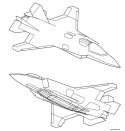
It was necessary to split the bay on the F-35 because there was a single large engine in the rear, and the fuselage was very short.

The J-XS has a long fuselage, and it has two engines. I cannot see the benefit of splitting the weapons bay on the J-XS.

F-22/J-20/J-35 style main weapon bay is located directly beneath S-ducts so the depth is limited.
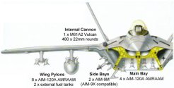
f22_schem_04.jpg

F-35 style weapon bay can carry bigger munitions
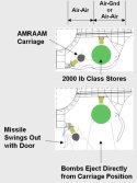
f35-bay.jpg
 

enroger

Junior Member
Registered Member
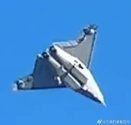
Anyone figured out what's the deal with the groove? It boggles the mind a bit, if it is as wide as Su-57 I would imagine maybe a similar tandem bay layout. But the groove is this narrow? Sure there is still space behind the intakes for two separate weapon bays but one would think filling up the groove will give you a bigger bay....
 

donnnage99

New Member
Registered Member
I think I figured it out (JK just an educated guess) - it features an adaptable bay. This was proposed on mcdonnell douglas jsf proposal (that eventually became the f-35). The bay inflate to accommodate a larger weapon and deflate to a flat surface for better stealth and/or aerodynamic characteristic(s). Someone who has the link to that patent please post.
 

Schwerter_

Junior Member
Registered Member
Anyone figured out what's the deal with the groove? It boggles the mind a bit, if it is as wide as Su-57 I would imagine maybe a similar tandem bay layout. But the groove is this narrow? Sure there is still space behind the intakes for two separate weapon bays but one would think filling up the groove will give you a bigger bay....
Can’t comment on whether the following is correct, but someone (the same guy who’s Zhihu post was posted in this thread a few pages back) guessed that the groove served a somewhat similar purpose to a so called “lambda shaped waverider” (which also has a pretty sharp groove on the underside) coming from a Chinese paper on hypersonic vehicles.
Apparently his guess is that the design provides more lift at higher (supersonic) speeds, similar to flanker’s groove between engines but optimized for higher Mach numbers.
Again I’m just passing on his personal guess, this is not confirmed to be true in any way
 

Deino

Lieutenant General
Staff member
Super Moderator
Registered Member
I think I figured it out (JK just an educated guess) - it features an adaptable bay. This was proposed on mcdonnell douglas jsf proposal (that eventually became the f-35). The bay inflate to accommodate a larger weapon and deflate to a flat surface for better stealth and/or aerodynamic characteristic(s). Someone who has the link to that patent please post.


Really? Can we stick to reality please … I must admit I think it is indeed positive that several new members entered the SDF and share their enthusiasm with the established „gang“ but we are not a forum where anyone should just spread any random idea and present it as a fact without proof or at least an explanation!

So NO, it’s NOT an educated guess, but just your randon idea and if it is educated, the elaborate …

As such all these hyper-bombastic claims made by some new members like this should be put into a perspective and explained or better not posted here.

:mad:
 

Schwerter_

Junior Member
Registered Member
I think I figured it out (JK just an educated guess) - it features an adaptable bay. This was proposed on mcdonnell douglas jsf proposal (that eventually became the f-35). The bay inflate to accommodate a larger weapon and deflate to a flat surface for better stealth and/or aerodynamic characteristic(s). Someone who has the link to that patent please post.
Could be, but pretty unlikely imo. SAC jet’s intake (from the looks of it) already reaches below the fuselage centerline so the groove we see would be there regardless of whether the main bay inflates or not.

patent attached, ive definitely seen more detailed diagrams but can’t seem to find it, this’ll have to suffice for now =(

Edit: okay this seems to be a not super related topic so I’ll refrain from making additional comments on the variable IWB design
 

Attachments

  • IMG_9391.jpeg
    IMG_9391.jpeg
    81.8 KB · Views: 79

enroger

Junior Member
Registered Member
Can’t comment on whether the following is correct, but someone (the same guy who’s Zhihu post was posted in this thread a few pages back) guessed that the groove served a somewhat similar purpose to a so called “lambda shaped waverider” (which also has a pretty sharp groove on the underside) coming from a Chinese paper on hypersonic vehicles.
Apparently his guess is that the design provides more lift at higher (supersonic) speeds, similar to flanker’s groove between engines but optimized for higher Mach numbers.
Again I’m just passing on his personal guess, this is not confirmed to be true in any way

Maybe SAC really loved their flanker after all. One possibility(though slim) is that they route their S-ducts into the center of the fuselage which allows the two weapon bays much more depth than traditional J-20/J-35 layout, but the groove seems too narrow for this explanation so idk. Hope we get high res photo soon.....
 
  • Like
Reactions: zbb

BillRamengod

New Member
Registered Member
Maybe SAC really loved their flanker after all. One possibility(though slim) is that they route their S-ducts into the center of the fuselage which allows the two weapon bays much more depth than traditional J-20/J-35 layout, but the groove seems too narrow for this explanation so idk. Hope we get high res photo soon.....
They call SAC SHENHOI for reason:D
 
Top